E_MOTION1.0 - A WEARABLE COMPUTING PROJECT
plays sounds by body movements
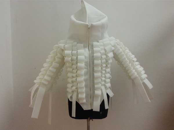
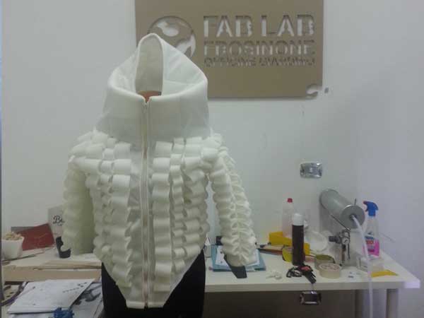
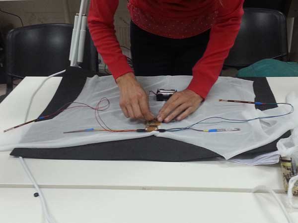
E_Motion1.0 is a Blazer with a removable electronic circuit, in its inner part, consisting of 4 Flex Sensors placed along the sleeves of the blazer, up to the shoulders and the elbows. This Sensors generate sounds making movements with arms like raising a shoulder or bending an elbow.
The project is made taking care about three important aspects: Mechanical, Electronics, Programming.
MECHANICAL:
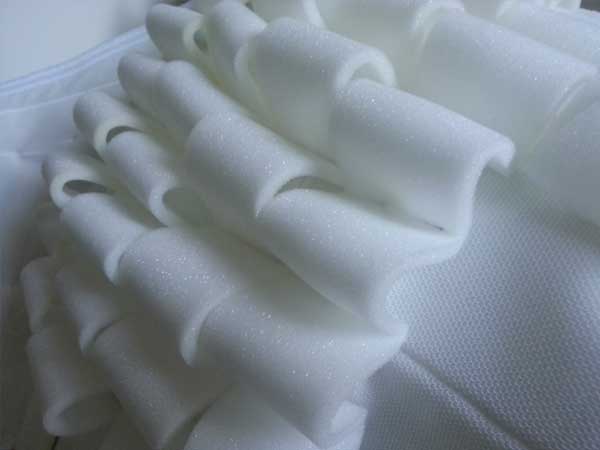
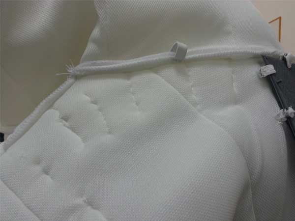
E_Motion1.0 is made of a three layers fabric according to a sandwich stratification. The two outers layers, which form the coating, are of a thin NON WOVEN FABRIC which locally in Italy calls "telina sotto palma" and the layer in the middle is of a Hypoallergenic Polyester with a thickness about 3 mm for a total of about 5 mm. I wanted this thickness to give to the design a solid structure. I thought about it as 3D object so I used the Polyester fabric to make outer 5 cm wide bands on the blaze.
ELECTRONICS:
The electronics circuit consisting of several components.
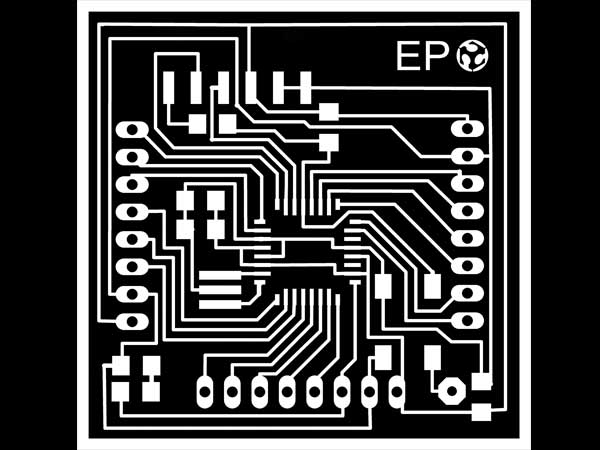
-The Fabkit by myself produced, which is the main board, with an Atmega328p as microcontroller.
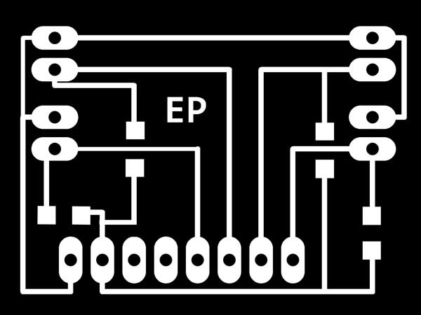
-An Input Shield, always produced by myself, to connect the sensor to the Board.
-A commercial Bluetooth Device to send data from the Board to PC.
-A 5V Battery assembled by myself for the power of the circuit.
-4 Flex Sensors connected by wires to the Input Shield.
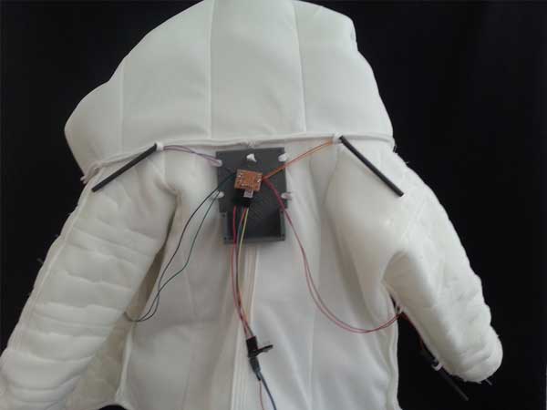
All the circuit, except flex sensor are inserted in a protective case that I had designed and printed in the Fab Lab. The case and the sensor with wires are inserted trough slots in the interior of the blaze.
PROGRAMMING:
This is the heart of E_Motion1.0. It works thanx input and output codes required to complete the project as a basic prototype.
Flex Sensors are setted on a sketch I wrote with Arduino Ide. The data collected by the microcontroller are sent via Bluetooth to PC. To translate this data in a sound output I need a second sketch which I wrote with Processing using the Beads Library.
TOOLS:
-RHINOCEROS, ILLUSTRATOR, PHOTOSHOP
-LASER CUTTING, 3D PRINTING, MULTINEEDLE MACHINE, SEWING MACHINE, MILLING MACHINE
-SCISSORS, NEEDLE, COTTON THREAD
DOWNLOAD FILES:
MECHANICAL:
PROJECT 2D
| ELECTRONICS CASE 2D
| ELECTRONICS CASE 3D
PROTOTYPING:
-3D PRINTING
| GCODE
| STL
-LASER CUTTING
| DXF
ELECTRONICS:
-FABKIT
EAGLE
| PNG
| RML
-SENSORS SHIELD
EAGLE
| PNG
| RML
PROGRAMMING:
INPUT
| OUTPUT

THE CONCEPT:
At the beginning of Fab Academy my project proposal was always about wearable and my idea was to study the right posture during fitness or physical activities. With my background as an Architect and doing some researches I quickly realized to reach that goal I should begin by one step easier. So I decided to focus on still body movement but work on a simple study of input & output to work in the sphere of performing arts.
E_Motion1.0 is the brainchild to study the body movement related to an output like light, vibration or sound. I decided to made this latter taking this and this projects as references.
So E_Motion1.0 is a dress for a performer that plays sounds moving the arms. Having four sensors my idea would be to produce a composition of four different sounds such as drums cymbals. To do that I need to elebarote data with a programming language like PURE DATA passing trough Processing.
The removable Electronic Circuit is inserted with a proctetive case inside the blazer.
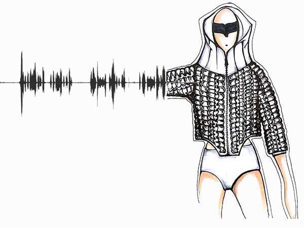
A sketch of the design
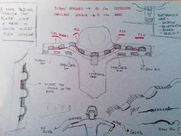
Thinking about the mechanism
PROGRESS:
I started to work really on my project the last 4 weeks of Fab Academy. Knowing that I have much work to do I decided to work managing the time in three weeks:
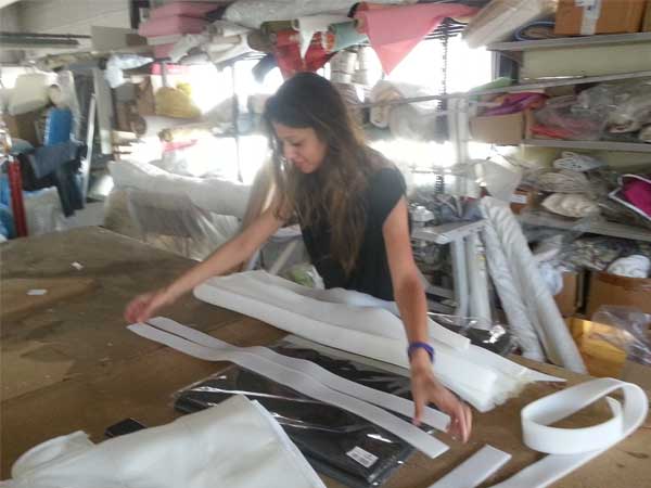
1st: Dress Design and Measuraments, the purchase of all materials and Circuit Design.
2nd: Fabric Cutting, Circuit Production and Testing of it, Interface and Sound output.
3rd: Tests and Solutions of possible problems.
4th: somenthing will go wrong and I'll be still working.
Done the time calendar I wanted subdivide my work into three sections to proceed cleraly.
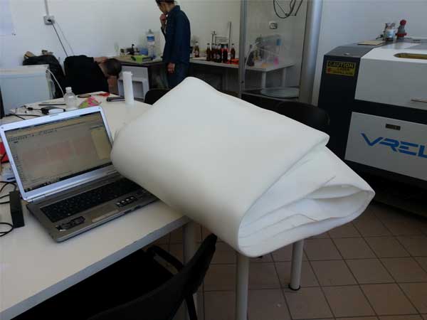
At the beginning my idea was to realize the project in Neoprene for the thickness(3/5 mm) and the elasticity of the fabric and more to confer a solid 3D structure to my project. I ordered online the product and it should have arrived in the 2nd week of the calendar but there was a shipping error and I deleted it. Here in Frosinone was difficult to looking for Neoprene so after a day of search I decided to find an alternative solution to made my project. I went in a local Matress Factory of and after explained the problem and my needs to realize in few time the project, I asked to proprietor if was possible made a quilt that I would cut in a second moment. The outcome was really succesfull! I obtained for free in one day the seam of a three-layer fabric of size 3x5 m (a quantity for at least 3 projects!).
MECHANICAL:
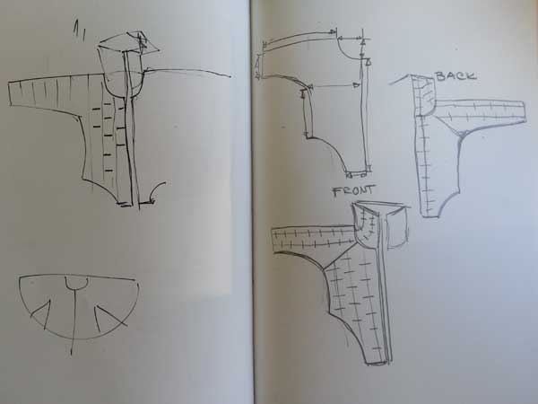
1-MAKING THE DRAW
2-CUTTING MODEL PAPER
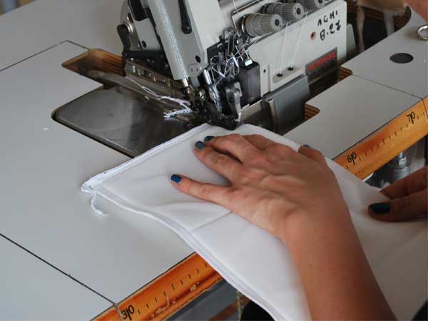
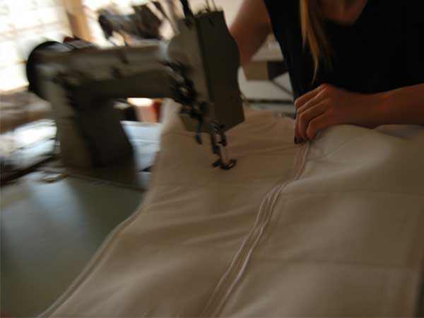
3-FABRIC PRODUCTION
4-CUTTING FABRIC
5-ASSEMBLY PIECES
6-DRAWING AND PRINTING ELECTRONICS CASE
7-MILLING ELECTRONICS BOARD
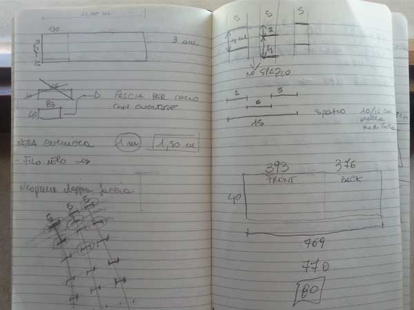
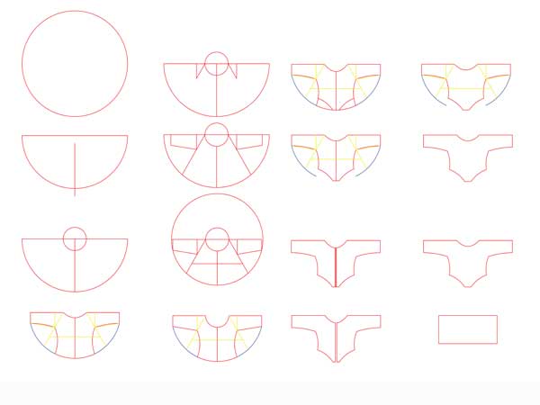
1. MAKING THE DRAW
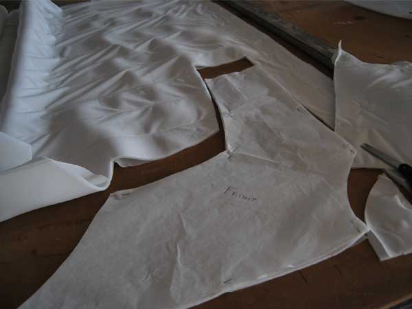
Starting from an handmade sketch I made a 2D draw on Rhinoceros to cut the model paper with the laser machine. I move from a Circle Technical to design the pieces for my blaze. With the help of a collegue I took my body measuraments which I have reported in the draw. The procedure to make the draw is very simple and doesn't have an absolute rule so it's possibile makes change as you want.
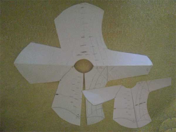
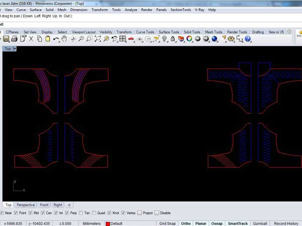
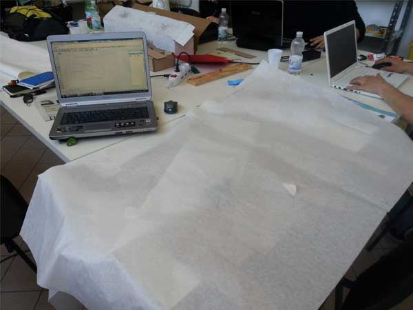
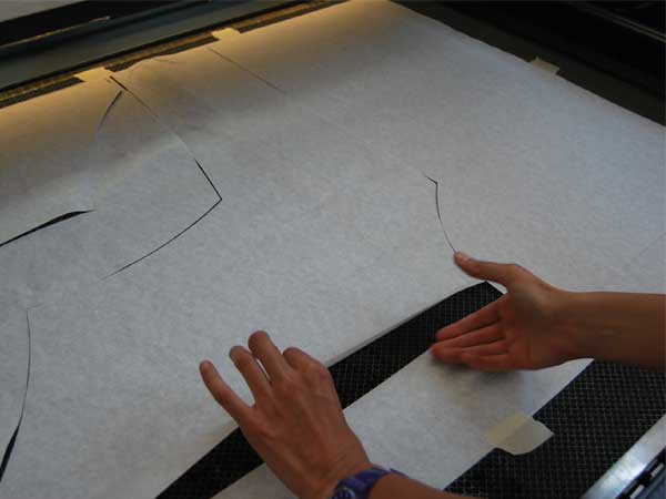
2. CUTTING MODEL PAPER
Once made the 2D draw, I prepared tables to cut the model paper with the Laser Machine. I exported the DXF files and I opened it in the Machine Software and I setted only cutting parameters. I put the paper in the machine, setted origin and did autofocus. Then I followed all the instruction before power up the machine and I started the cut. I did this step in a very short time.
PARAMETERS TO CUT MODEL PAPER:
LASER CUTTER VREL CO2 ME-1300
CUT: 400(Speed); 8(Power %); 6(Power Corner %)
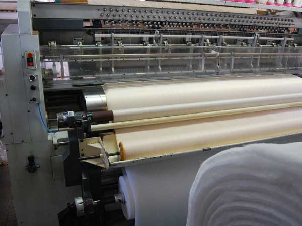
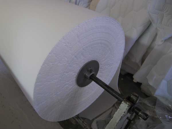
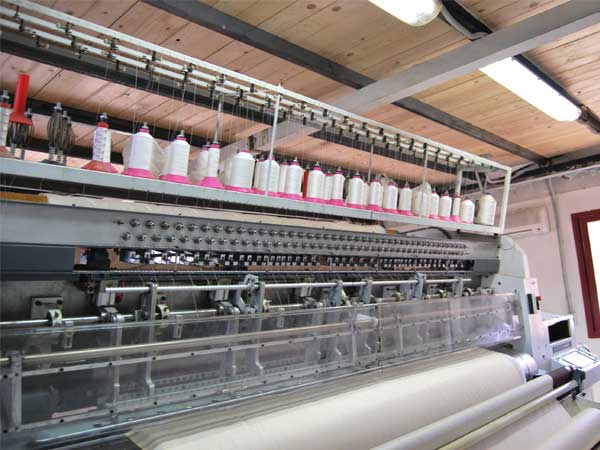
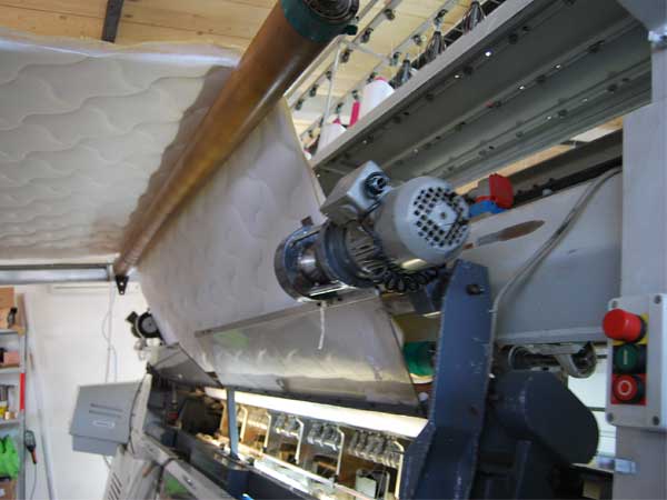
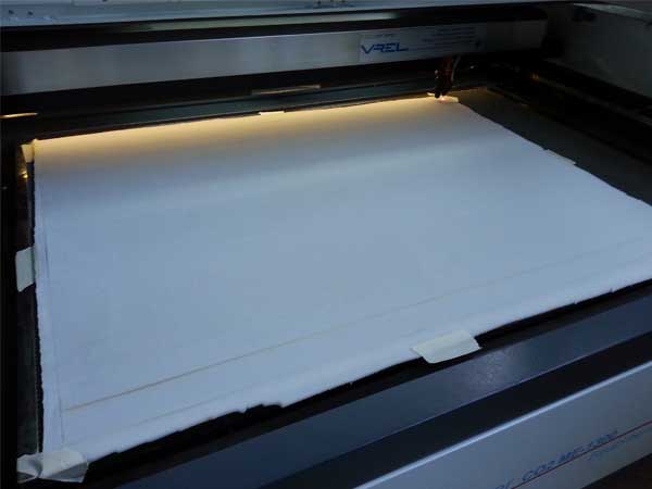
3. FABRIC PRODUCTION
As explained before, the Fabric to made mechanical part of my project was produced in a local Matress Factory, Dormire Trade. The Fabric was sewn by a Multineedle Machine Meca Targhet model, as a quilt size 5x3 meters. It is composed of three layers according to a sandwich stratification. The two outers layers, forming the coating, are of a thin NON WOVEN FABRIC which locally calls "telina sotto palma" and the layer in the middle is of a Hypoallergenic Polyester with a thickness about 3 mm for a total of about 5 mm. Time to quilt was about 30 minutes.
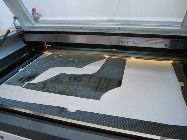
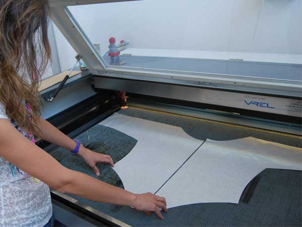
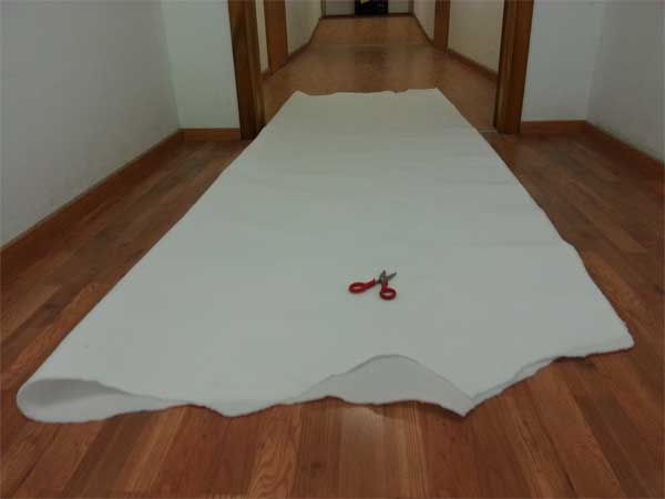
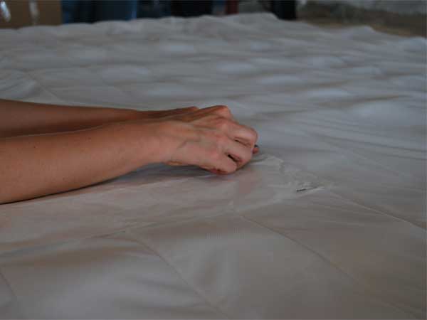
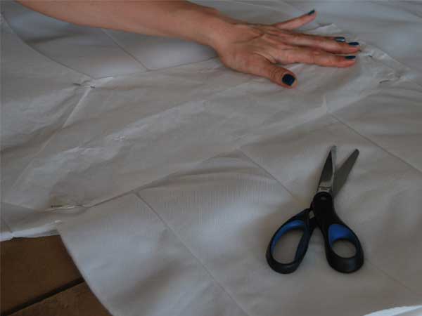
4. CUTTING FABRIC
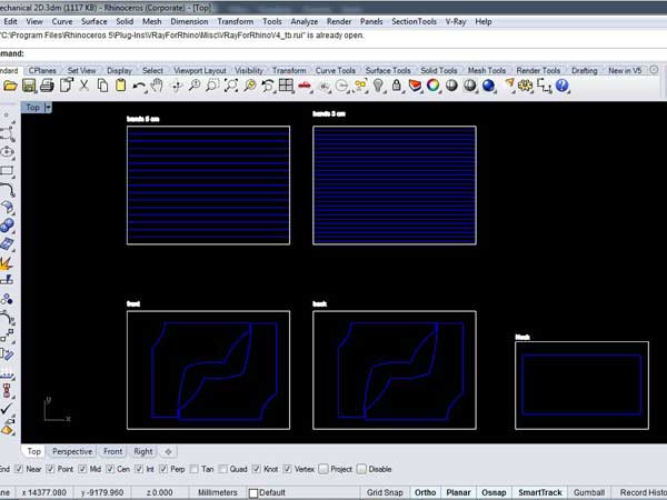
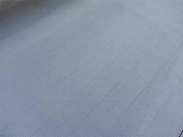
Once ready the quilt the next step was to cut the fabric using the shape of the model paper. Having three layers sewing together by warp, I felt was better cut the quilt with scissors rather than Laser Cutting. I used again the machine only to cut the bands to apply on the blazer. From a Polyester Fabric (4 meters of lenght) I cutted a series of rectangles sized according to the laser machine plane, to made the bands. So again I made a DXF file and I lasered the Polyester.
PARAMETERS TO CUT POLYESTER:
LASER CUTTER VREL CO2 ME-1300
CUT: 300(Speed); 10(Power %); 8(Power Corner %)
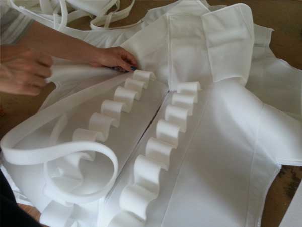
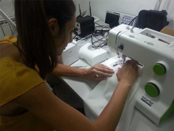
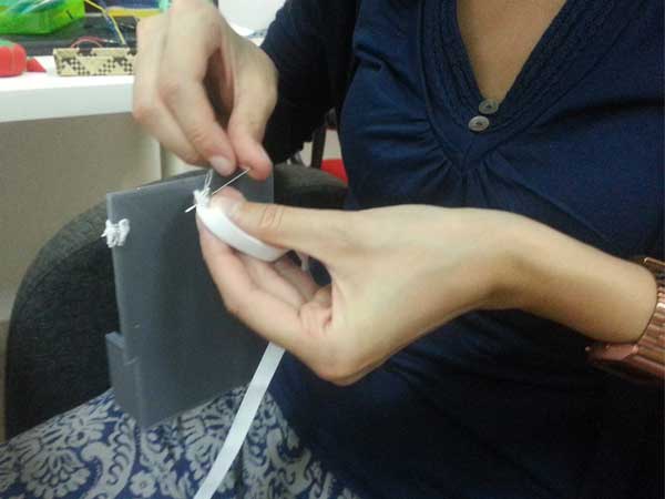
5. ASSEMBLY PIECES
Once ready the quilt the next step was to cut the fabric using the shape of the model paper. Having three layers sewing together by warp, I felt was better cut the quilt with scissors rather than Laser Cutting. I used again the machine only to cut the bands to apply on the blazer. From a Polyester Fabric (4 meters of lenght) I cutted a series of rectangles sized according to the laser machine plane, to made the bands. So again I made a DXF file and I lasered the Polyester.

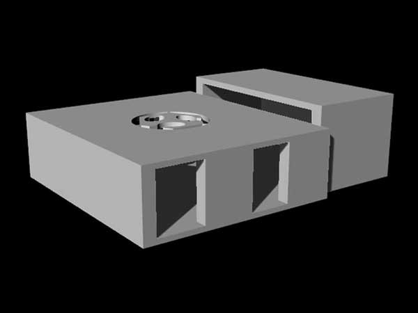
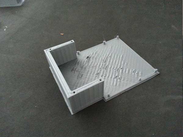
6. DRAWING AND PRINTING ELECTRONICS CASE
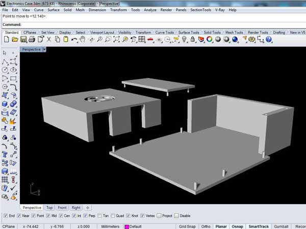
During the COMPUTER-AIDED DESIGN WEEK 2 I modeled an electronics case that I decided to use for my project to gain time and save costs of total budget. I did only some dimension variations and I exported the STL Files to made Gcodes with Cura Software for the 3D Printing Machine.
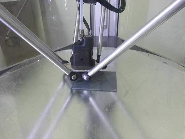
PARAMETERS TO PRINT THE CASE:
DELTA WASP 60×100
Print Speed: 120 (mm/s)
Printing Temperature: 185 (C)
Bed Temperature: 65 (C)
Fill Density: 20 (%)
Filament Diameter: 1.75 (mm)
Filament Material : GREY PLA
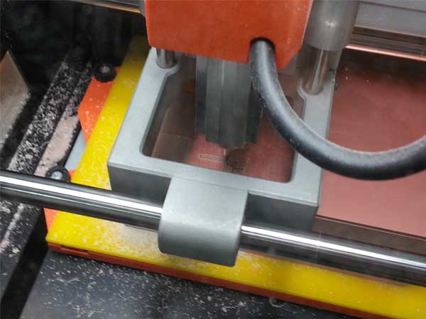
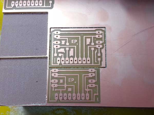
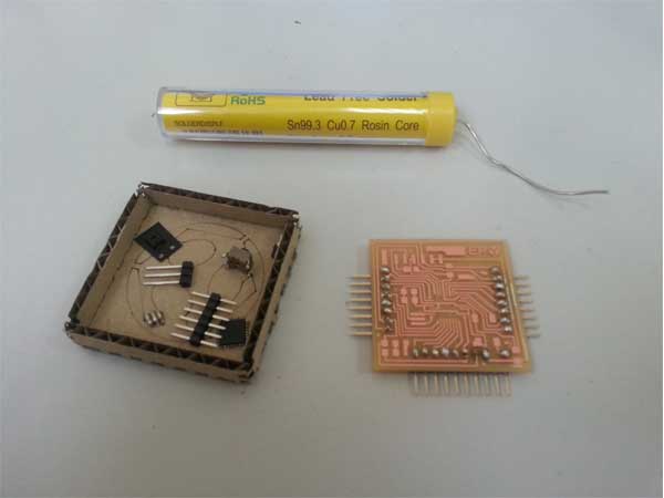
7. MILLING ELECTRONICS BOARDS
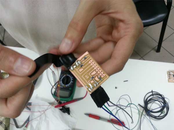
To made the electronic circuit of my project I need two boards. The Fabkit with the microcontroller and a shield for the sensors that I used. Unfortunately the first Fabkit I produced during the Fab Academy stopped working, so I had to made another one. Instead the the Input Shield has been designed specifically for the connection of the Flex Sensors, so I draw it in Eagle and then I made the PNG files. Once I had all the files I made the RML files on FabModules and I milled the boards using Panel Software for the Milling Machine.
PARAMETERS TO MILL BOARDS:
ROLAND SRM-20 MACHINE
Traces: tip 1/64
Interiors: tip 1/32
ELECTRONICS:
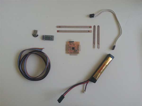
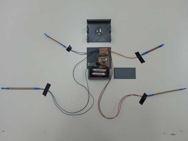
About Electronics Component E_Motion 1.0 has a removable circuit inserted in it's inner part. It consist of following parts:
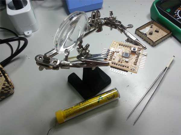
1. A FabKit that is the main board made by myself also during the INPUT DEVICES WEEK 10, with an Atmega328p microcontroller. The others components that I put in the board are:
-capacitor 0.1 uf n° 2
-capacitor 10 uf
-smt pcb button 6 mm
-resonator 8 Mz
-resistor 10 K
-resistor 499 Ω
-red led smd
-header 6 pins
2. An Input Shield, always made by myself, to connect the Flex Sensors the FabKit. On this shield I put the 4 resistances 10 k each one for a Flex Sensor.
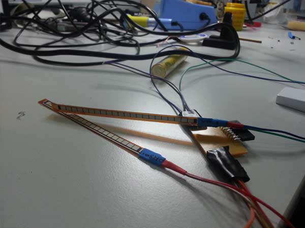
3. 4 Flex Sensors connected by wires to the Input Shield. Each sensor has two pins, one for VCC and the other for the GND. The Resistance of the sensor changes when the metal pads, which are on it, are on the outside of the bend. So as the sensor is flexed, the resistance across the sensor increases. For more technical specifications is possible read the datasheet in the references.
4. A commercial Bluetooth Device to send data from the Board to PC with 4 pins (TX,RX,VCC,GND).
5. A Power of 4.8 V consisting of 4 alkaline batteries 1.2 V assembled by myself to feed the circuit.
In a schematic way I can describe the functioning of the circuit:
The performer moves bending elbows and raising and lowering the shoulders so the resistance of the Flex Sensor changes accordingly. Input Data are sendig via Bluetooth from the Fabkit to the PC and an audio device emits sounds.
All the circuit, except flex sensor are inserted in a protective case that I had designed and printed in the Fab Lab. The case and the sensors with wires are inserted trough slots in the interior of the blaze.
REFERENCES:
Atmega 328
Flex Sensor
Bluetooth Device
PROGRAMMING:
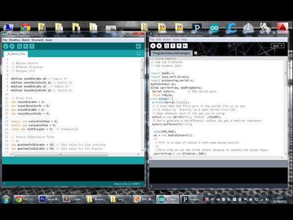
To programm my project I wrote two sketches of code, one for the Input with the Arduino Ide and the other one for the output with Processing. In the Ide I declared and setted the 4 Flex Sensors, mapping each of them with a minimum and maximum values (which are the equivalent of the quietness position and flexion one of the sensors). Then I split the range in 10 positions. I modified the baud from 9600 to 115200 for the reading of data via bluetooth in the serial monitor.
With Processing I wrote the code for output using the sound Beads Library to emit sounds. The communication between Ide and Processing is trough serial port where is connected the Bluetooth device (on my pc usually is COM10).
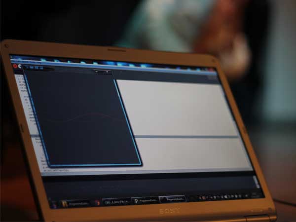
First Prototype:
E_Motion 1.0 is a basic Prototype. It is in absolute my first made project and I'm very satisfied of the goal achieved in so little time. In general the project works and it is completed in each tasks. Some problems during evolution of the work have done several things to change, from the design of the blaze to the insertion of the electronic circuit.
Certainly now I have a greater knowledge of base from which working on the project to develop and improve it.
The total cost of the project is changed from the initial budget: from about 120 euro (130 USD) it was about 70 euro (80 USD).
RELATED LINKS:
APPLICATIONS AND IMPLICATIONS
INVENTION,INTELLECTUAL PROPERTY & INCOME
PROJECT DEVELOPMENT