Week10 - input devices
Measure something: add a sensor to a microcontroller board that you've designed and read it.
CLASS WEB PAGE:
http://academy.cba.mit.edu/classes/input_devices/index.html
DOWNLOAD FILES:
-INPUT DEVICE: EAGLE | PNG | IDE
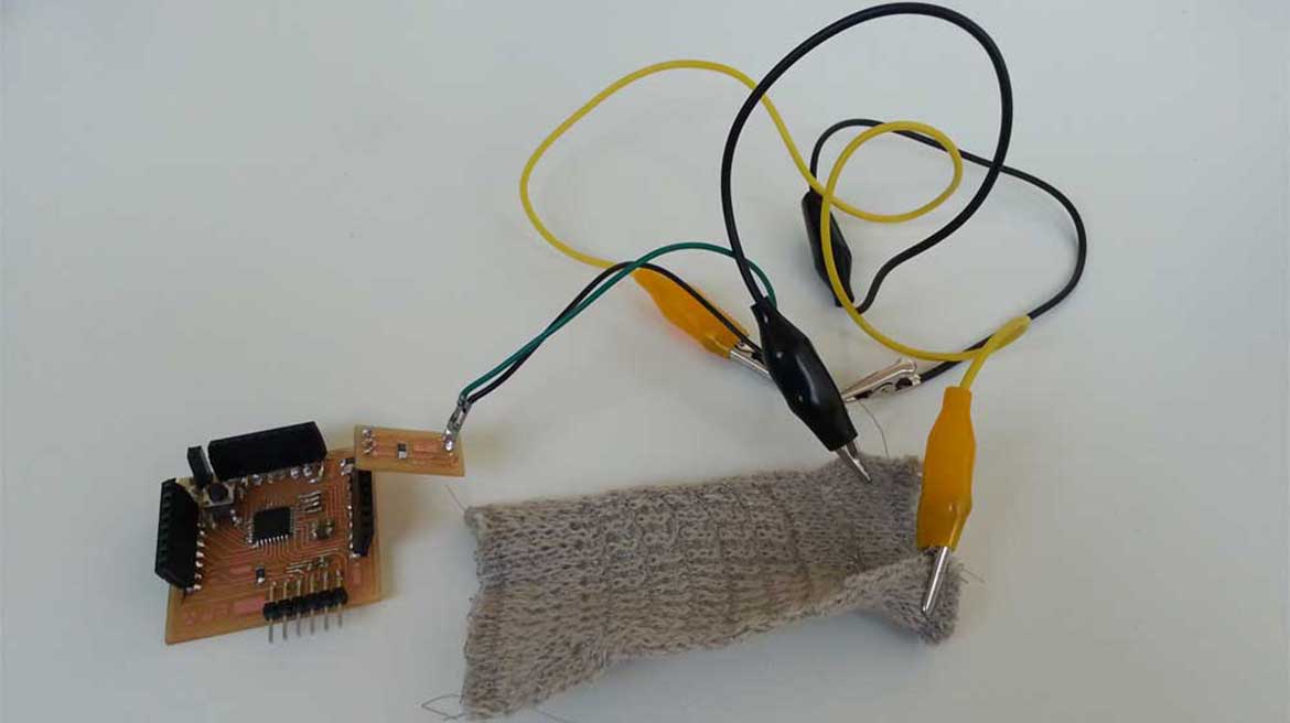
This week we had to choose one input and make a board to make it work. Instead of using an Attiny 44, I made a Fabkit, to use from now on, and a small shield (thinking about my final project) with a stretch sensor and its resistor. I took the files of the Fabkit 'Here'. Initially my intention was to make a small change on the board. I wanted to put a 6 pin header in the bottom part that is conected to MOSI, MISO and SCK, for making it easy to bootload. But during the milling test of the basic Fabkit board at the Fab Lab, we had a problem with the Z setting of the Roland Machine, so the time available to us was very small. At the end I mill the basic Fabkit board and my little shield.
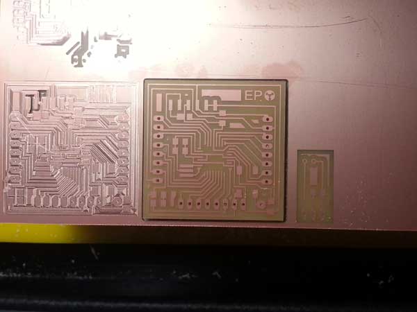
First Phase: Milling.
I started milling the Fabkit Board. This time I had trhee png file to put in the Machine: one for the traces with 1/64 tip and two for the holes and interior files with 1/32 tip. After I used Eagle software to design the shield and I exported trhee other png files. On the FabModules I prepared the rml files.
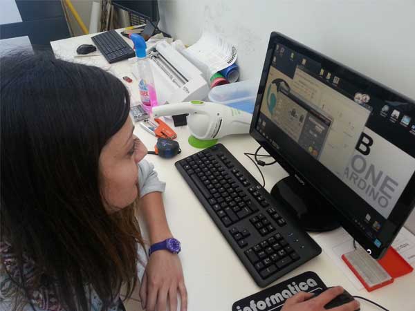
setting the milling
my FabEle & input device
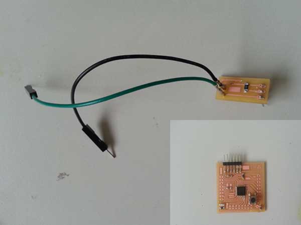
soldering FabEle & input device
making bootloader of my fabkit
Second Phase: Soldering.
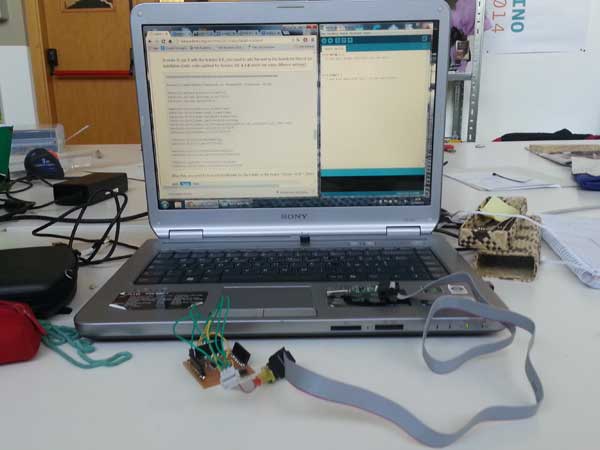
Starting to solder my Fabkit I realized that some components at our disposal were wrong... so at the last I had to decide to finish the assignment using my Shield on Arduino Board. hen I have all the right components I'll finish my Fabkit and I'll go ahead with the programming of it.
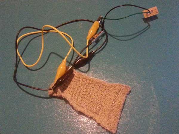
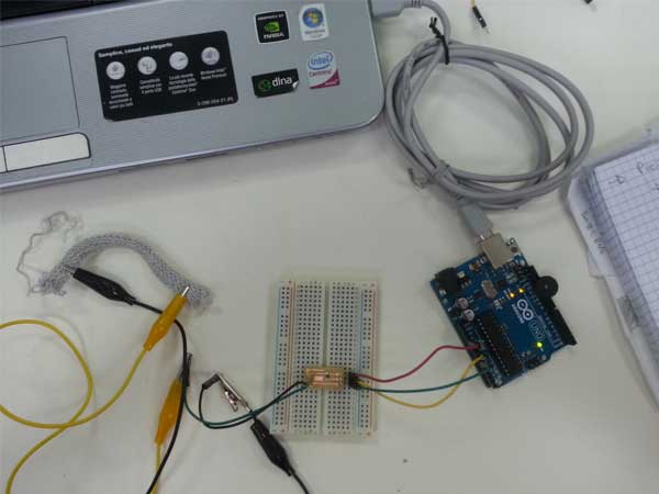
THE STRETCH SENSOR CONNECTED ON ARDUINO AND THEN WITH MY FABKIT: