
Lessons
- Final Project Proposal
- Lesson 1 - principles and practices and project management (Jan 29)
- Lesson 2 - computer-aided design (Feb 5)
- Lesson 3 - computer-controlled cutting (Feb 12)
- Lesson 4 - electronics production (Feb 19)
- Lesson 5 - 3D scanning and printing (Feb 26)
- Lesson 6 - electronics design (Mar 5)
- Lesson 7 - computer-controlled machining (Mar 12)
- Lesson 8 - embedded programming (Mar 19)
- Lesson 9 - molding and casting (Mar 26)
- Lesson 10 - input devices (Apr 2)
- Lesson 11 - composites (Apr 9)
- Lesson 12 - output devices (Apr 16)
- Lesson 13 - networking and communication (Apr 23)
- Lesson 14 - mechanical design, machine design (Apr 30)
- Lesson 15 - interface and application programming (Apr 30)
- Lesson 16 - applications and implications (May 14
- Lesson 17 - invention, intellectual property, and income (May 21)
- Lesson 18 - project development (May 28)
- Lesson 19 - project presentation (Jun 4)
Lesson 13
- What I did on this week:
- I made the hello.bus.45 board (a master one and a node one) that Neil created.
- I programmed it using an AVRmkII and a FabISP.
- I tried to change ("hack") the C code (but didn't get success with that).
- I tested the boards and tried to troubleshoot the code I wrote (also, no success, because of the C libraries on my PearPC).
- The board was working well (with Neil's code, obviously)!
- The master board:
- The node:
- Video of the boards working:
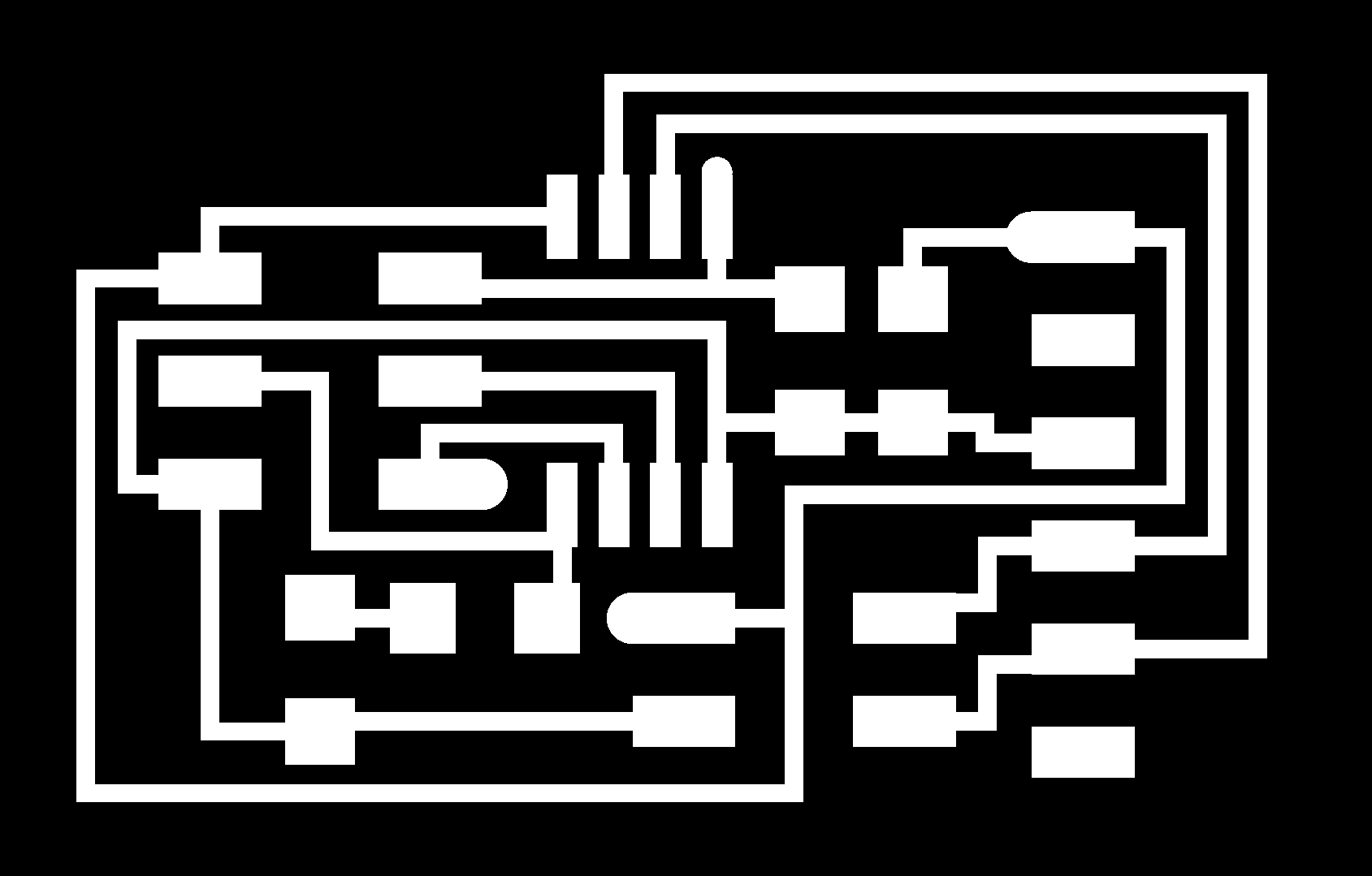
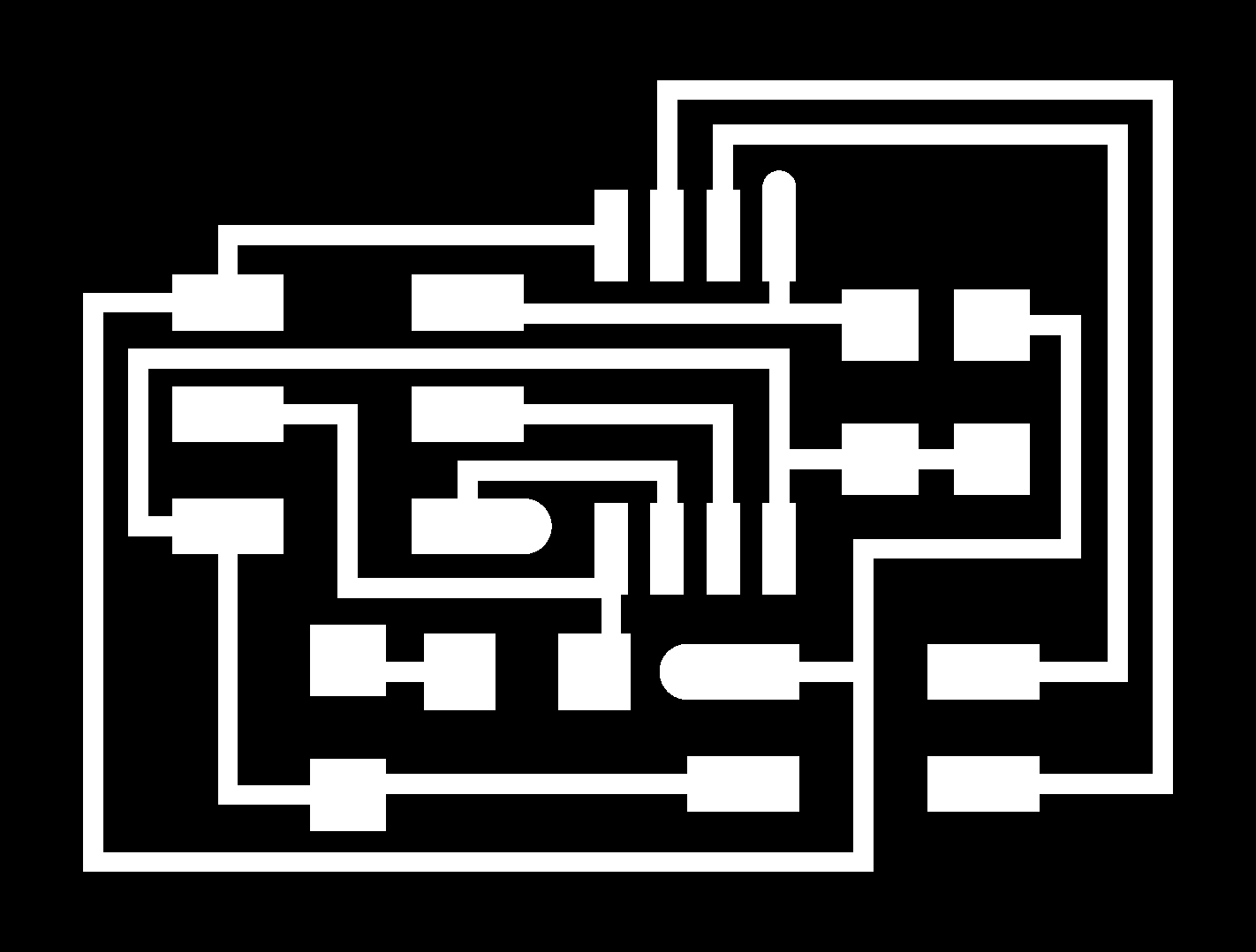
- Mill the board with those pictures: for the bridge: traces and interior
and for the nodes: traces and interior - Solder all of the components (here is the board schematic: bridge and node
- After that, get your FabISP or AVRISP and your FTDI cable, and get the master board connected to the FTDI and to the AVR.
- Then, download the code from here and extract the archive to a folder.
- After that, go to you terminal (terminal or cmd, whatever there is on your OS), navigate to the folder using the cd command, and then type in this command: sudo make -f hello.bus.45.make program-usbtiny. If you are using an AVRmkII from Atmel, change the end of the command to avrisp2.
- Then, open the C code with your favorite text editor (I recommend Notepad++ for Windows, TextWrangler for Mac and GEdit for Linux) and change the node id (in the #define node_id '0' line) from 0 to 1 (because the master board is number 0).
- After that, disconnect your master board from the FabISP or from the AVR and connect a cable from the master 4-pin to the node 4-pin.
- Then, repeat step 5 for your node.
- After that, open Arduino IDE and open Serial Monitor. Then write in the prompt box 0 or 1.
- Some images of the board:
- How I got to this result (tutorial):
NOTE: the master board and the bridge board are the same.

Copyright 2010. Designed by htmltemplates.net