Computer Aided design
1. Weekly Brief Summary
This week I tried some design tools.
I used Adobe Illustrator and Inkscape, ImageOptim for 2D design tool, Fusion360 and FreeCAD for 3D design tool.
And I used these tools to express the final project.
2. Weekly Assignment Requirement
Assignment
- model (raster, vector, 2D, 3D, render, animate, simulate, …) a possible final project, and post it on your class page.
Learning outcomes
- Evaluate and select 2D and 3D software
- Demonstrate and describe processes used in modelling with 2D and 3D software
Have you
- Modelled experimental objects/part of a possible project in 2D and 3D software
- Shown how you did it with words/images/screenshots
- Included your original design files
3. Assignment Work Planning
-
2D(Raster) design Tools
(a)Compress an image when submitting a task
(b)Create a final project image
(c)Brush up a sketch of a final project -
2D(Vector) design Tools
(a)Create Japanese traditional pattern
(b)Comparison between Illustrator and Inkscape -
3D design tool
(a)Express the final project in 3DCG
(b)Drawing production
4. Description of Assignment Work
A. 2D design tools
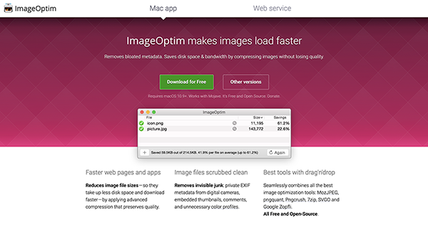
ImageOptim[Raster]
I tried using it because FabLab Kamakura’s instructor introduced the image compression app in Local Session.
1. Open the App
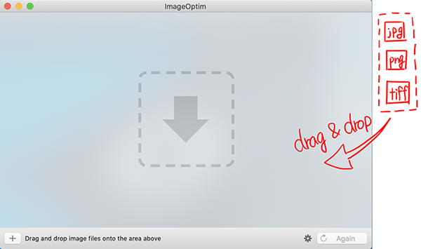
2. Read Image Files
Also, you can add an image by [+] in the lower left.
An image desired to be compressed is read therein.
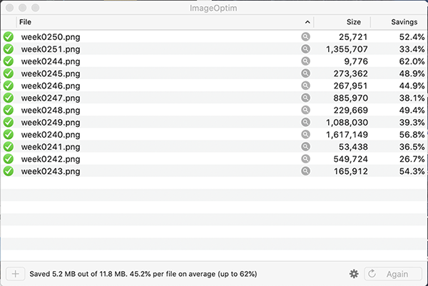
In this way, the file size is reduced by about half.
(It took about 8 minutes to compress)
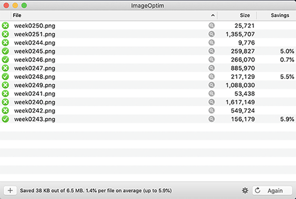
Attempted to compress the same image again.
There are things that can be compressed and things that can’t be compressed.
I can’t make it any smaller, so I’ll click Preview or Photoshop should be used to reduce the size itself.
3. Evaluate
When I try to compress more than 10 photos, my computer is so slow that I can’t do any other work.
As a work procedure, I recommend that you first reduce the image size using Photoshop or Preview, and then use this app to reduce the data capacity.
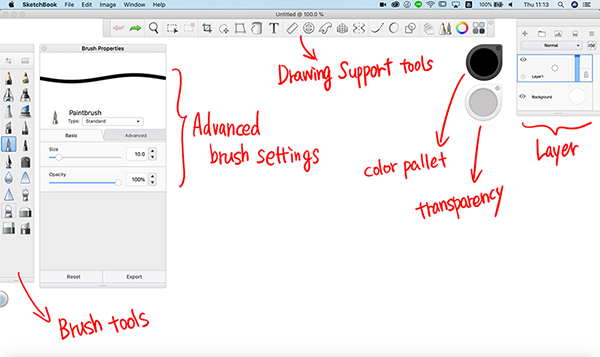
SketchBook[Raster]
This is a free drawing app I’ve been using for personal work for two years.
I feel UI is easier to use than Photoshop in terms of drawing.
I especially like this app because I can reproduce the coating of the copic marker.
1. Open the App
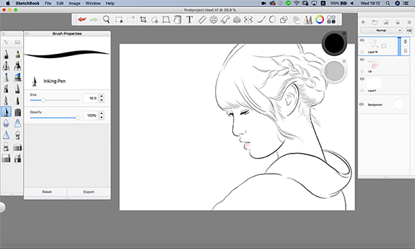
2. Brush-up idea sketch
This time I used a pen tablet called Wacom Intuos Pro.
Wacom Intuos Pro can be used to automatically detect writing pressure and express natural drawing.
①Draw a Model
The pen tip to use is [Inking Pen].
This kind is easy to use because it is compatible with the pen tablet.
Set the size of [Brush Properties] to [16].
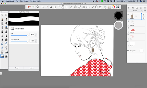
②Read the Pattern of Kimono
Draw out the pattern of the pattern made by Adobe Illustrator as an image (how to make this pattern later).
Click [⌘+option+shift+S] to save as [PNG] file.
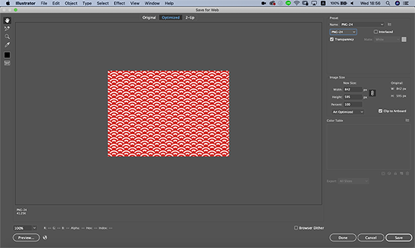
A stored image is read by opening a photo icon in the upper right.
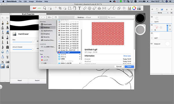
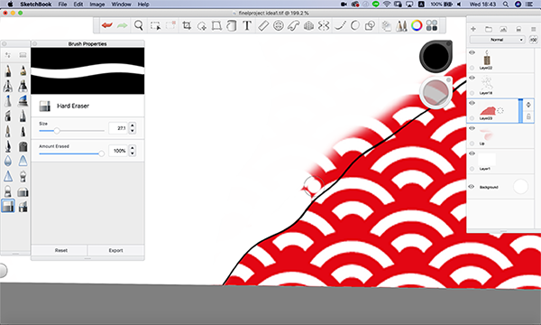
A part protruding from the kimono is erased by an eraser tool.
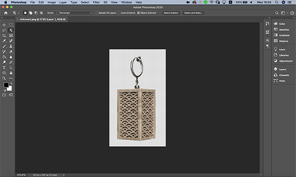
③Load a 3D Model
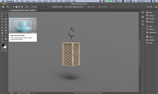
Read the rendering image created by Fusion 360 in Adobe Photoshop and delete the background etc.
(The Fusion 360 rendering image will be created later.)
Use the Object Selection tool to crop the image.
 ↓
↓
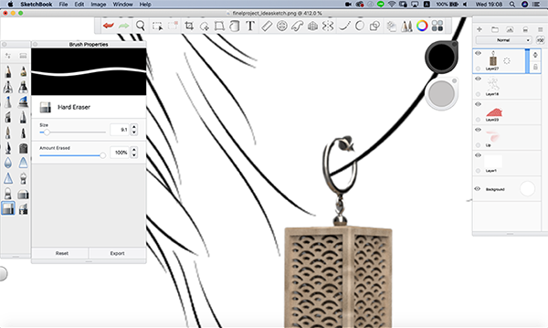
A cut-out image is stored in an [PNG] file and read in the same way as before.
Adjust the parts of the earring with an eraser tool.
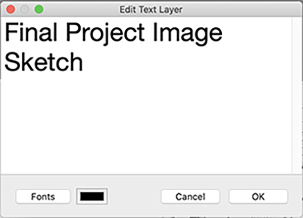
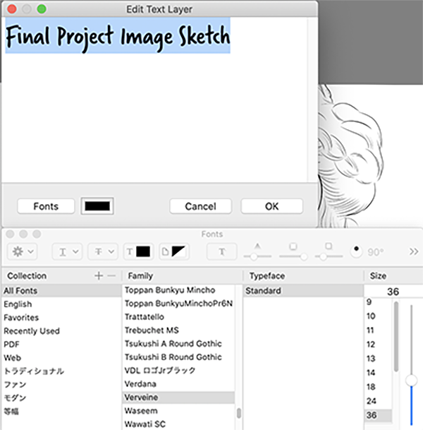
④Create Title
Click the letter [T] in the toolbar to open the text tool.
You can select various font designs by clicking [Fonts].
↓
⑤Save
Sketchbook can be stored in the following format.
- TIFF
- JPEG
- PNG
- BMP
- Adobe Photoshop PSD
- Adobe Photoshop TIFF
- Pixlr PXD
This time, save it in PNG format.
↓

3. Evaluate
The sketchbook has a layer function, so you can manage the pictures on a task-by-task basis.
I also like the brush tool that allows me to customize the UI to suit my taste.
Adobe Illustrator[Vecter]
It will be 8 years since I used this app.
So I trust this app for functionality and ease of use.
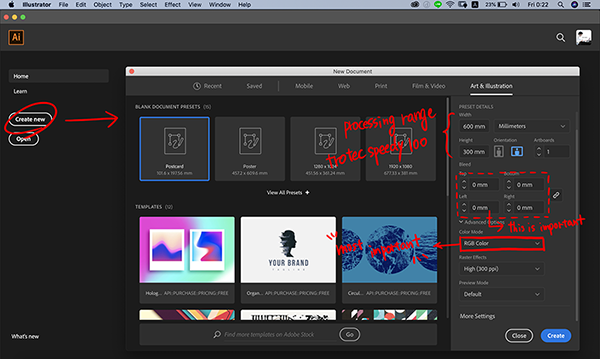
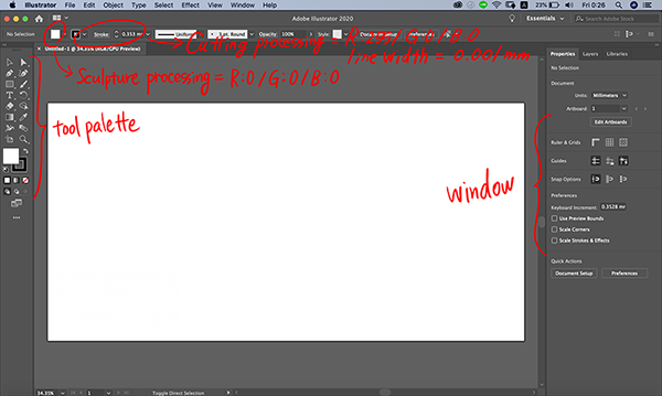
1. OPEN the App
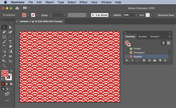
2. Create Japanese traditional pattern
Make “Seigaiha”
Meaning of Seigaiha
The pattern of infinitely wide waves is a pattern of wishes for happiness that will continue into the future forever and for people’s hopes for a peaceful life.
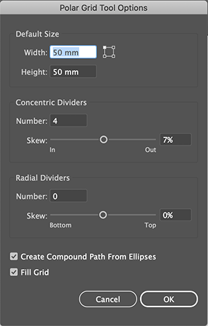
① Polar Grid Tool
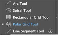
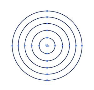
A concentric circle is created as the basis of the Seigaiha.
To set diameter=50mm、Concentric Dividers=4.
IMPORTANT
・Create Compound Path From Ellipses
・Fii Grid
Put a check in.
↓
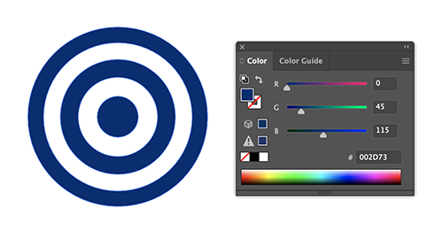
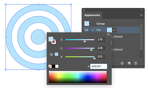
② Color
Set one’s color.
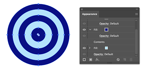
③ Appearance
[Window]→[Appearance]→[Add New Fill]
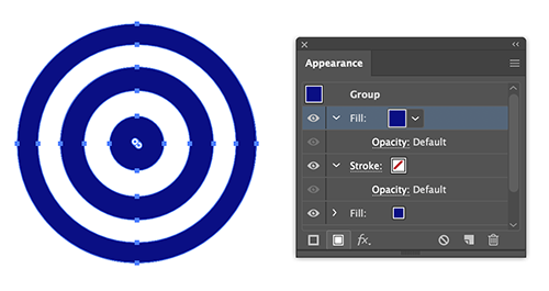
Add a different color to the paint added to.
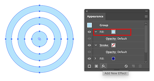
Select[Add New Effect] with New Colour Selected.
Select [Convert to Shape]→[Rounded Rectangle].
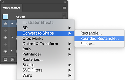
If you set the radius of the square circle to [25 mm], it becomes a circle with a diameter of 50 mm.
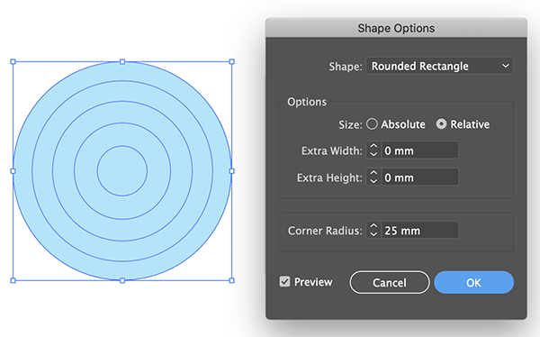
Move the [New paint] hierarchy below the first paint you made it.
④ Pattern
Create a design from [Object]→[Pattern].

Click[OK]→[Pattern Option] opens.
Set to [Tile Type]→ [Brick by Row]. Brick Offset→[1/2] Adjust the intervals between the figures freely.
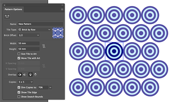
The pattern turned upside down.
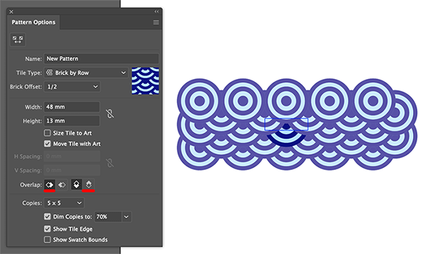
Set [Overlap] to [Left in Front]&[Bottom in Front] to solve the problem.
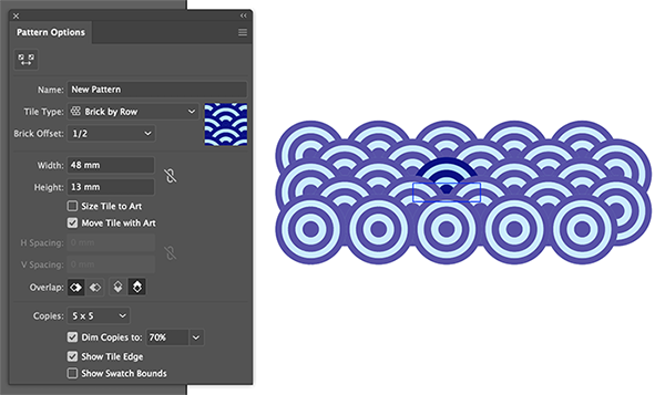
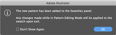
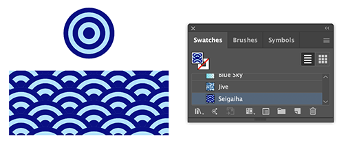
Press [OK] to add a new pattern into [Pattern Options].

If the file name is “Seigaiha”, it’s OK!
3. Evaluate
[Polar Grid Tool] and [Pattern Options] were easy to use. It is easy to manage because you can name the created pattern.
Inkscape[Vecter]
Since the inkscape is a free vector editing app, FabLab Kamakura uses it as a teaching for workshop.
This time I have used it to see if it can be used in the same way as Adobe Illustrator.
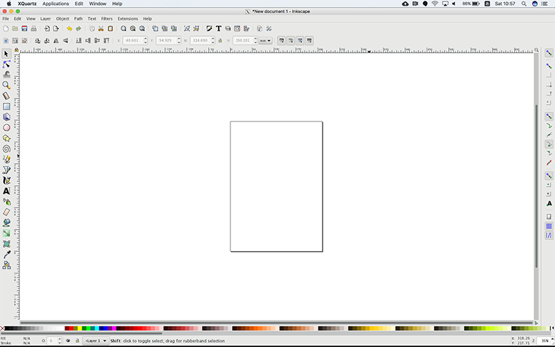
1. Preparation and running Inkscape
Download and install XQuartz from xquartz.macosforge.org .
2. Open the App
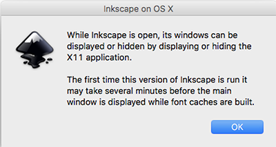
While Inkscape is open, its windows can be displayed or hidden by displaying or hiding the X11 application.
The first time this version of Inkscape is run it may take several minutes before the main window is displayed while font caches are built.
↓
3. Make “Seigaiha”
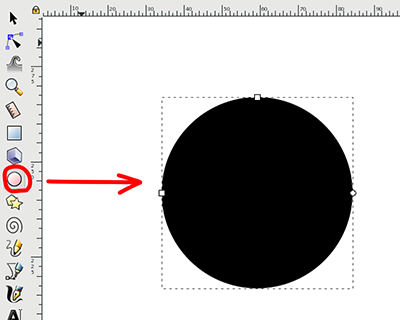
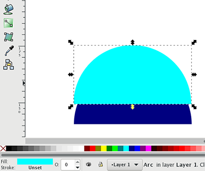
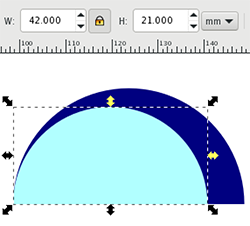
① Circles, Ellipses, and Arcs Tool
If you drag [control]+[shift] in the direction of 45°, you can draw a perfect circle.
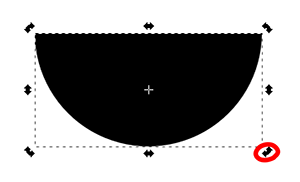
If you move the “node” while pressing [control] , you can create a semicircle.
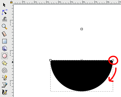
As the semicircle is formed downward, the figure is clicked twice to display the rotary tool.
↓
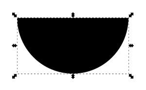
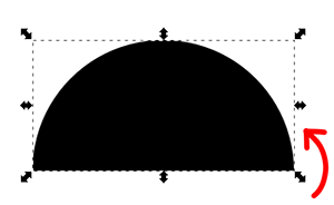
Transform the semicircle upward.
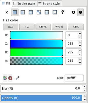
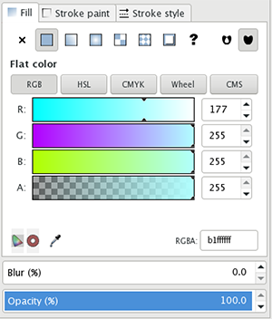
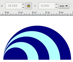
② Change Color
Select a color from the color palette at the bottom of the screen.
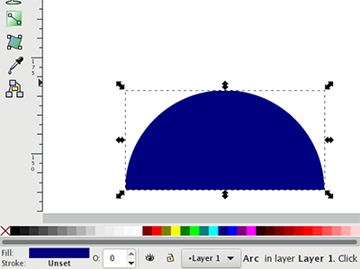
Click [control+D] to duplicate a semicircle. Change the color of the duplicated semicircle.
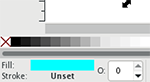
↓
Set the color details in the [color palette].
↓
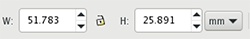
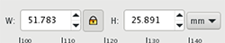
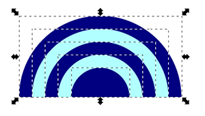
③ Reproduction of Figure
Lock up when resizing.
↓
A reproduced semicircle is made in height [-4 mm].
 ↓
↓
This work was repeated to increase the number of semicircles.
I used the dropper tool when I was coloring.
 ↓
↓

⑤ Alignment of Figures
A duplicated semicircle is selected to align the figures.
Alignment Panel Appears on [control]+[shift]+A.
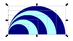
Select [Center on vertical axis] to arrange the figures.
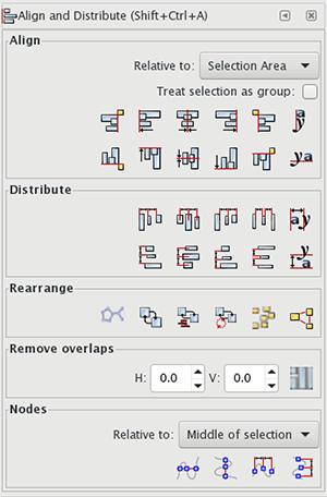
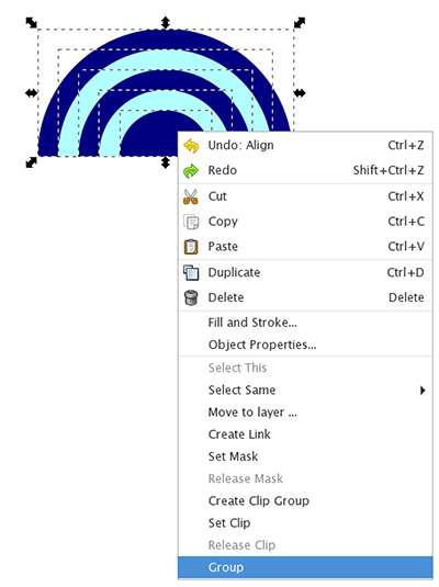
[Group] aligned figures
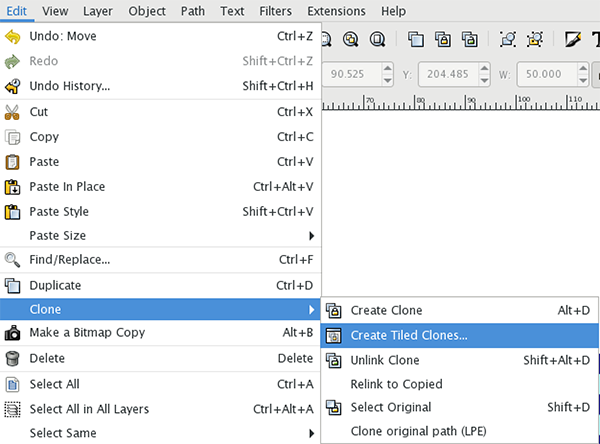
⑥ Pattern Creation
Duplicate the figures in the order of [Edit]→[Clone]→[Create Tiled Clones].
↓
[Create Tiles Clones] is seen.
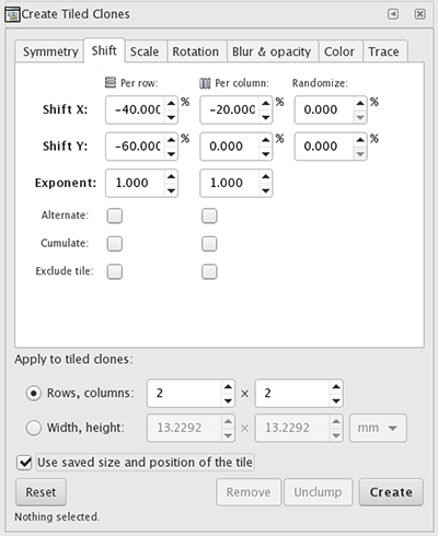
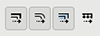
The only tab I use this time is [Shift].
I don’t use anything else.
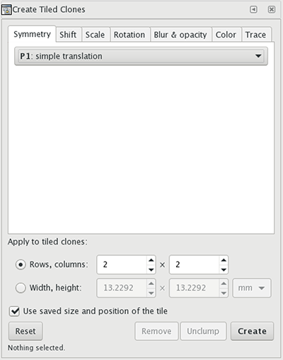
[Shift] is set as follows.
Enter a number and click [Create].
↓
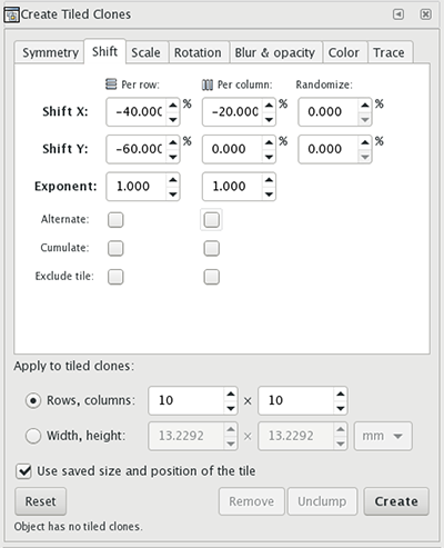
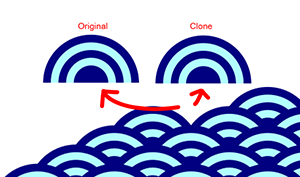
OK!
There are only two figures on the top left.
One is the original figure.The other is cloning.
A figure as a starting point is deleted.

As the origin data are under the clone, the clone is arranged on the outermost surface and then deleted.
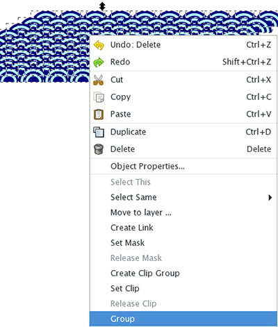
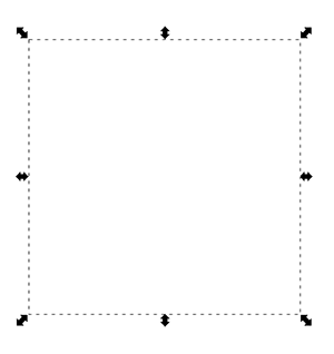
⑦ Creating an Original Pattern
[Group] the replicated clones.

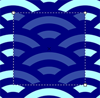
An object to be a source of a pattern is created by cutting out a graphic by using [rectangular tool].
In that case, set the [Snap Bar] at the right end of the screen so that the snap fits the guide of the object (you can turn it all on for now).

A [rectangular tool] uses a [node tool] to create a suitable size.

Create within this range.

Both a rectangular object and a pattern object are selected, and a clipping is performed by clicking [Object]→[Clip]→[Set].
↓

OK!
The original object has been made!
Create an original pattern from [Object]→[Pattern]→[Object to Pattern].
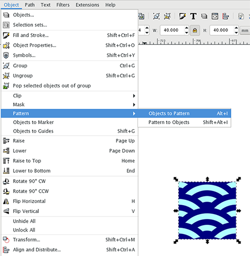
Click to add a new “pattern6579”.
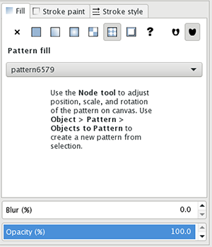
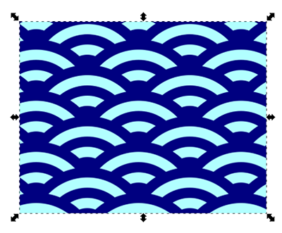
I will check using [rectangular tool] immediately.
From the pattern of [Fill] panel, “pattern6579” created earlier is selected.
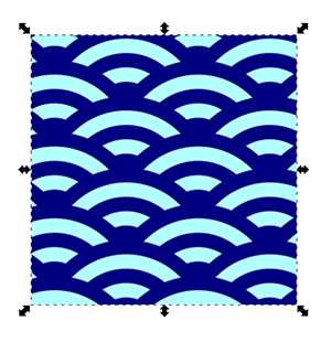
OK!
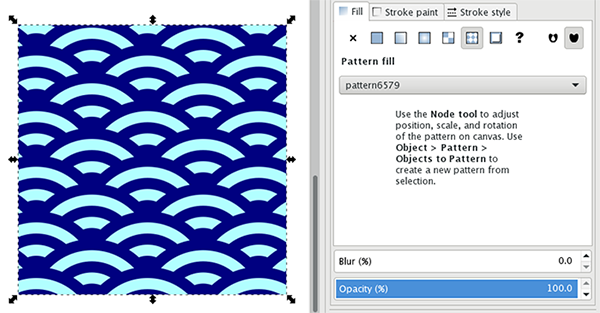
⑧ Deformation of Figure
If the pattern frame is fixed, the figure in the pattern is deformed when the figure is deformed.
↓
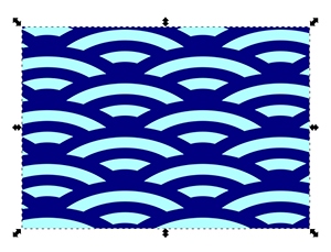
So when the fixing tab of the pattern frame is turned off, only the figure is deformed.
↓
Seigaiha pattern is complete!
4. Evaluate
There were some parts that were difficult to use when I was used to Adobe Illustrator, but I could do the same thing in general.
However, there are a lot of steps to make pattern fill, and you need to input numbers multiple times.
It’s hard to see the results because there’s no preview.
B. 3D design tools
Fusion360
I used SolidWorks as a student, but I couldn’t use it well at that time.
After graduation, I couldn’t use SolidWorks on my PC, and I didn’t use 3DCAD App at all.
However, when the Fusion 360 service, which allows 3DCAD App to be used in Mac environments.
So I got used to Fusion360 better than SolidWorks’s UI.
1. Download & Install
You must create a new account for Autodesk before downloading.
2. Open the App
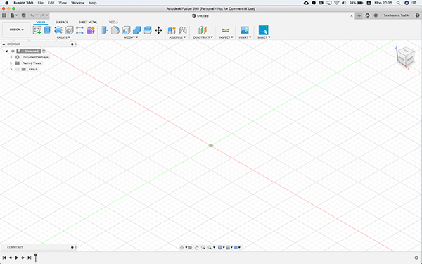
3. Final Project Modeling
① Size of the Accessory
First of all, you need to determine the approximate size of your accessories before designing them.
This time, we will design the traditional Japanese lighting fixture, the “Andon.”
In addition, the idea of the lighting mechanism has not been decided yet, but I will make it the size that is supposed to contain the electronic parts such as LEDs in the future.

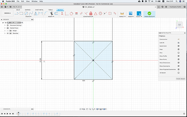
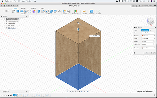
Create a rectangular parallelepiped with width, length = [20mm] and height = [35mm].
 ↓
↓
②Create “Seigaiha” Pattern
Create a patterned pattern of accessories. When I drew the blue sea waves with Fusion, I used the mathematical approach shown below.
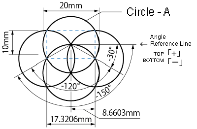
Create multiple concentric circles using the circle tool, and delete the overlapped lines using the trim tool.When the underlying column is formed, create it with the replication tool.
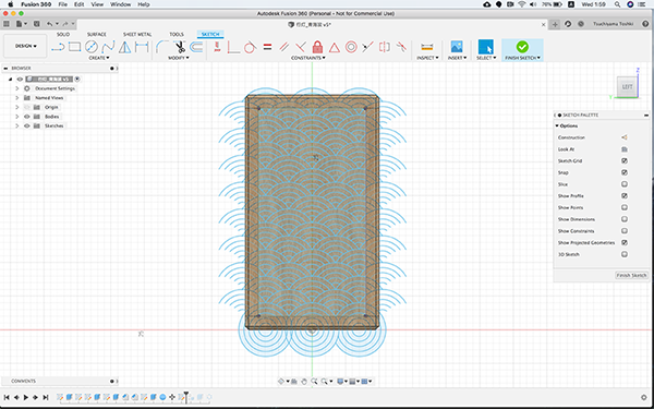
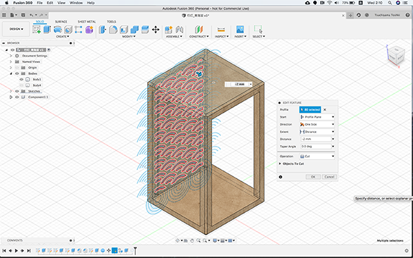
③Clipping
Cut out the created pattern from the extrusion tool.
 ↓
↓
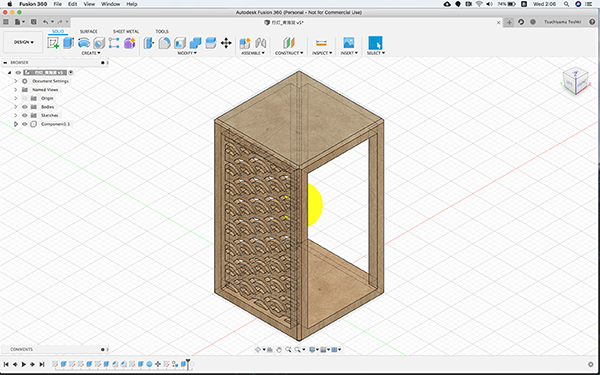
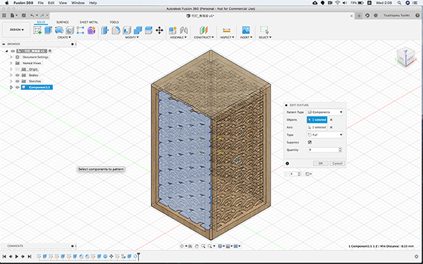
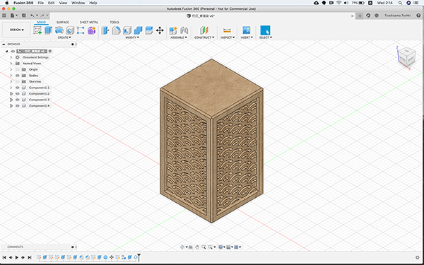
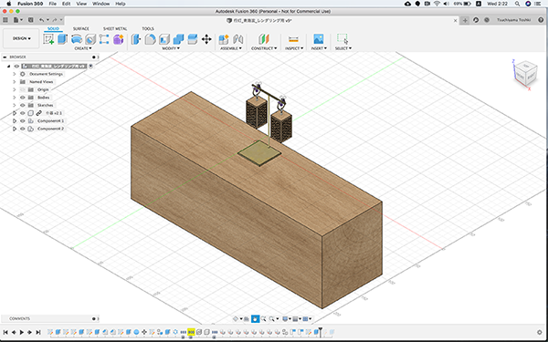
④Component Replication
This cut-out feature will be componentized and placed on four sides with the replication tool.
 ↓
↓
⑤Parts Assembly
Create the accessory parts and include them in the design.
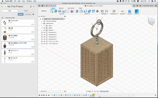
I also made brass furniture to create a sense of accessory size.
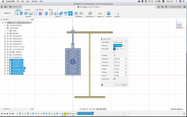
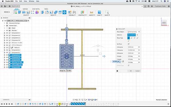
⑥Movement and Replication
Replicate the componentized design using the moving tool.
At this time, if the moving tool is not started first, there are times when it is impossible to copy the moving tool well.
 ↓
↓
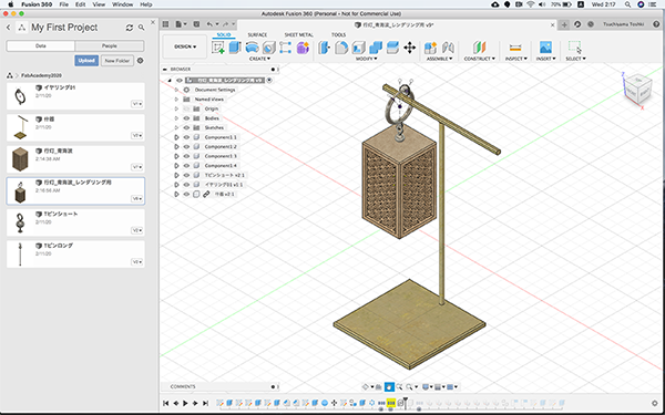
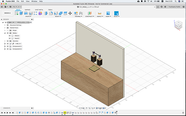
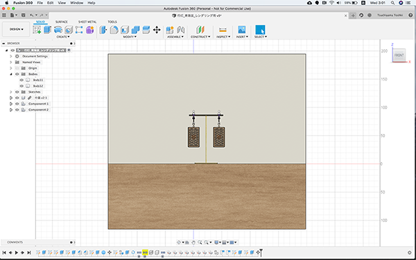
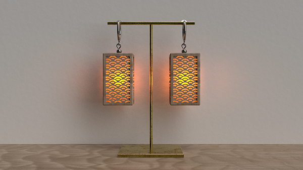
⑦Construction of Environment
A photographing booth is created for rendering. Tables and walls are created.
 ↓
↓
[Frontal View]
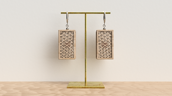
⑧Rendering
I created two patterns of images this time when the LEDs are shining and when they are not.
In rendering when the LED is shining, the environment is made dark so that the light is conspicuous.
[Normal ver.]
[Lighting ver.]
4. Evaluate
The variety of texture is increased compared to the one I used before, and I was able to set the kind of wood and the texture of metal in detail.
I felt that it is important to create an environment (a furniture and a shooting booth) because rendering allows more realistic images of the atmosphere.
ZbrushCore
ZbrushCore is not like Fusion360 or Freecad.
This application allows you to model sensibly, just like sculpting or clay modeling.
This is not a numerical controlled modeling, but a sensory modeling with a pen tablet.
Since you can model as if you were drawing a picture, it is easy to operate even for beginners, and you can use it as a 3D modeling tool. It can be used as an introduction.
1. Download & Install
ZbrushCore is a paid software.
It is currently available for about $179.
Sometimes you can get it for an affordable price that includes a Wacom pen tablet.
I recommend checking Amazon often.
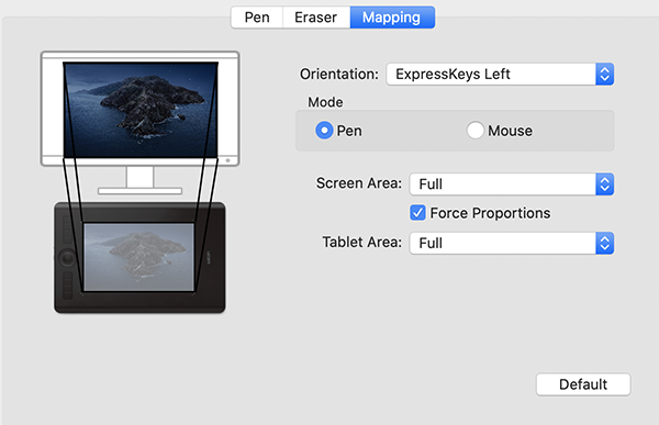
1. Building the Work Environment
ZbrushCore recommends using a pen tablet.
It is recommended that you purchase a pen tablet that is suitable for your computer’s monitor size.
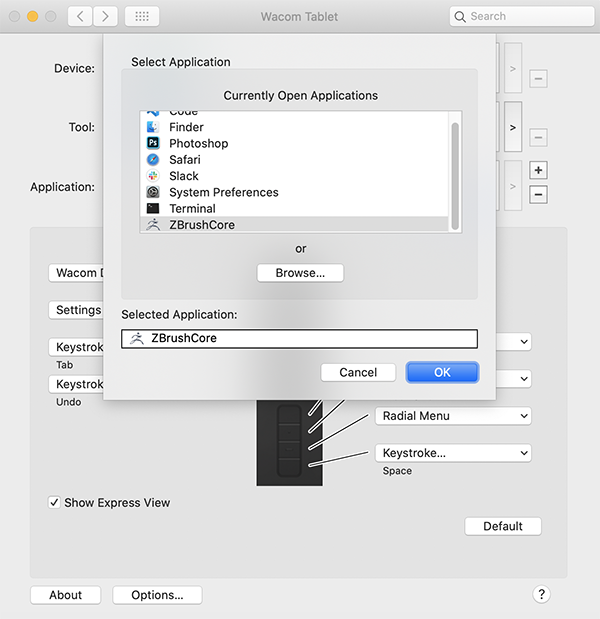
Click [System Preferences] > [Wacom Tablet] and configure ZBrushCore settings.
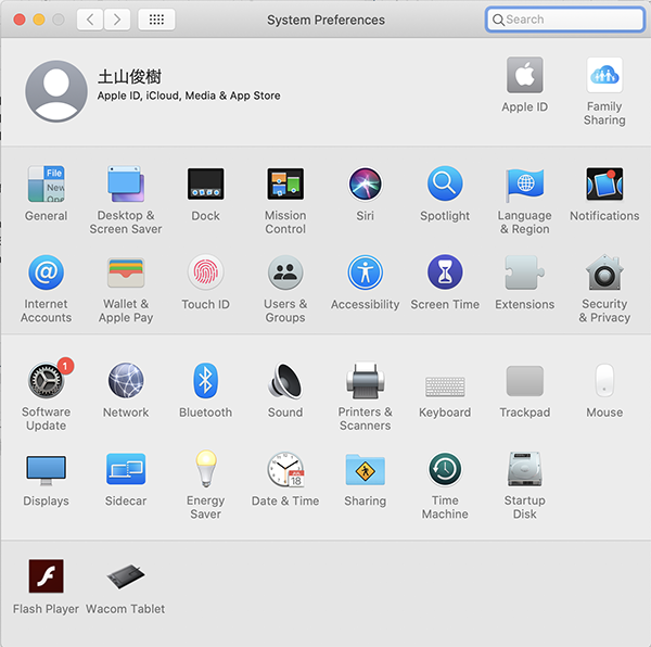
↓
Click [+] in [Application] and add [ZBrushCore].
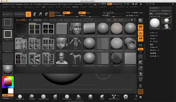
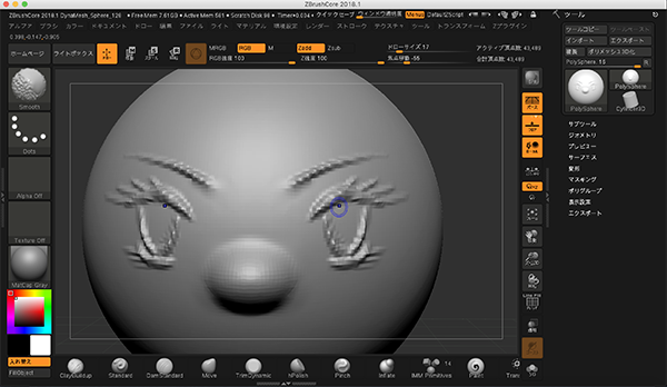
2. Open th App
When you start the application, you will find various modeling data templates in the [Lightbox].
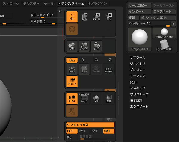
ZBrushCore allows you to model left and right targets, and you can choose the target axis from among XYZ by selecting [Transform] > [Enable Geometry].
A round cursor in the screen shows the part of the screen that is linked to the pen tablet.
There are four different view control panels on the right side of the screen.
[Frame] ・・・displays a 3D model on the entire screen.
[Move] ・・・ Move the pen to the button and drag it in the direction you want to move it, to move your viewpoint.
[Zoom 3D]・・・ Move the pen to the button and drag it to the outside/inside of the screen. It’s an expansion/reduction of perspective.
[Rotate] ・・・Place your pen on the button and drag your viewpoint in the direction you want to rotate it. Rotation.
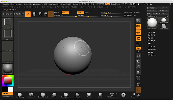
At the bottom of the screen, you can change various types of brushes.
In the upper part of the screen, you can change [Brush Size] and [Brush Strength] of the selected brush.
3. Types of Brushes
The brushes can change the shape of the model to fit the selected shape.
I can use it like a paintbrush to add clay, sculpture, or color to your model.
On the Mac, you can reverse the effect of the selected brush by holding down the [option] key as you manipulate the brush.
(1)ClayBuildup
(2)Standard
(3)DamStandard
(4)Move
(5)Smooth
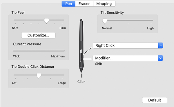
I have it set to allow me to switch to the [Smooth] brush when I press [Shift].
4. Evaluate
ZBrushCore allows you to model sensibly, just like modeling with n-clay, so you can get an organic I specialize in representation.
However, since modeling is dependent on proficiency, it will take some time to be able to produce a convincing work of art.
I found it to be quite time consuming.
This time, I tried to sculpt a humanoid character as a tutorial, but it didn’t go well. We were unable to produce satisfactory modeling data.
5. Description of Important Weekly Learning Outcome
This time at 2D design tool, I tried to do the same thing as Adobe Illustrator using Inkscape.
I was a little confused about the operability, but I wish I could get used to it in the future.
I didn’t really understand the difference between the body and the components on the Fusion 360, so I made the same mistake several times.
I was impressed because I was able to create a photo-like image in the rendering.
6. Links to Files and Code
- Final Project Image Sketch [png]
- Seigaiha pattern with Adobe Illustrator [ai] / [svg]
- Seigaiha pattern with Inkscape [svg]
- Final Project with Fusion360 [f3z]
![[svg]](../../week03/files/seigaiha_illustrator.svg)