electronics design
.
lecture / slide: Fabacademy 2015 03.04D Lesson06: Electronics Design MIT CBA Electronics Design.
topics: components, circuits.
assignment: redraw the echo hello-world board, add button and LED, check design rules, make it and simulate its operation!-
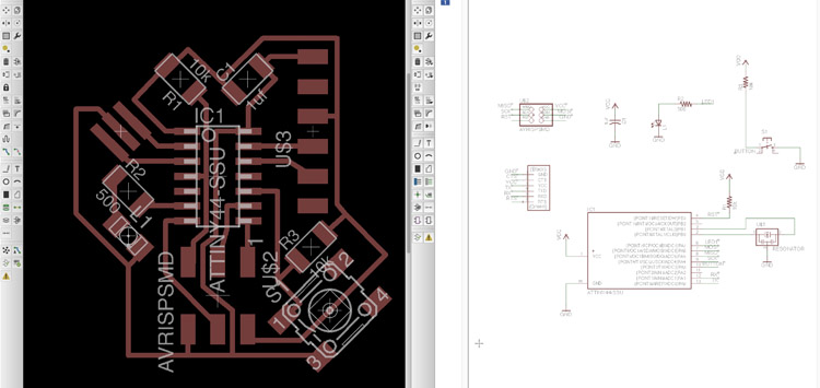
experimentation: According to Neil's template of the Hello World Board the first step was to install EAGLE in order to produce the electronics board. It starts by important the fab-library, importing all the necessary items, laying them out and understand the basics of electronic circuits. Once everything is attached properly (better triple check) the board is ready to go into a schematic plan that will be milled later on but still need to be organized to make the traces valid: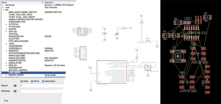 The yellow traces need to be changed for proper traces and components have to be moved around, in the best case pretty compact but also keeping in mind that some of the items need space to be connected with cables or reached by hand, as the button. If changes are needed, e.g. exchange of components both files will be updated in real time. For the tracing: components are able to be translated and rotated, it just needs some time to figure out the layout of the board. Basically you can also design round traces or make them crazy and also unneccessary long. I decided to put some elements in 45 degrees to make it more interesting:
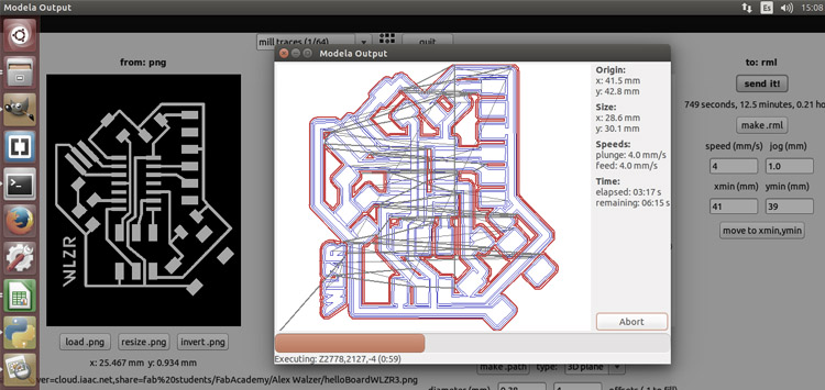
 Using GIMP to offset the boards printing layout and get the border for production I was good to go back to use the FabModules for the Roland MXD-20 desktop milling machine and put in the settings needed:
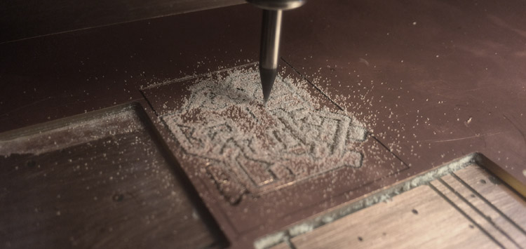
 The milling machine working:
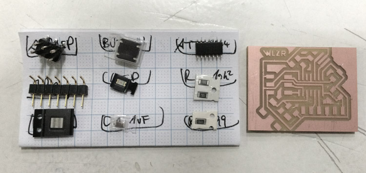
 As the milling job was done and the board removed from its plate I collected the necessary parts, looking both to my EAGLE sketch and the initial template by MIT:
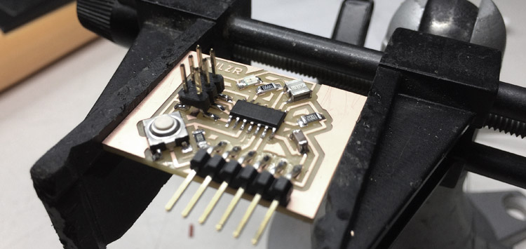
 It took around one hour to solder all the pieces. Special attention has to be given of course to the direction of the ATtiny44 and the SMD LED. The other components are unpolarized and can be put in any direction. Unfortunately the button was faulty and got stuck after triggering it some time so I went back to the soldering station, removed the old button and placed the new one. Since the board is pretty compact some joints were tricky to make but finally it worked out and looks pretty nice:
 to be continued next week when we are looking to embedded programming!
.
files: Files wlzr Fab Academy '15 // w06.
bookmarks / links: Atmel ATtiny 24 / 44 / 84 datasheet Instructables Soldering tips and tricks.
review: Fabacademy 2015 03.11B Review06: Electronics Design-

Any content on these pages by Alexander Nikolas Walzeris licensed under a Creative Commons
Attribution-NonCommercial-ShareAlike 4.0 International License