Week13 - Networking & Communication
Design and make a 3D mold (~ft2), and produce a fiber composite part in it
CLASS WEB PAGE:
http://academy.cba.mit.edu/classes/networking_communications/index.html
hhttp://academy.cba.mit.edu/content/tutorials/akf/networking_serial_bus.html
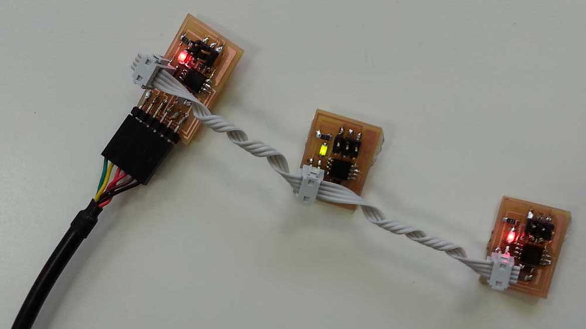
This week the assignment was about networking and communication. The aim of the exercise was to design and build a wired &/or wireless network connecting at least two nodes. For this week assignment I made three boards and connect them with a 4th pins connector. I made one bridge for master and two nodes for slaves. The bridge board is connected to a computer via a FTDI cable. The two node boards are connected to the bridge board.
DOWNLOAD FILES:
hello.bus.45.bridge PNG
hello.bus.45.node PNG
hello.bus.45.c
hello.bus.45.make
First Phase: Milling & Soldering
For my exercise I need to mill the Hello.bus.45 both for the Node that for the Bridge which I downloaded in the Serial Asynchronous of the Class page. As usual now I made the fabmodules files and I mill the board with the Roland Milling Machine always following the same procedure ( Tip 1/64 for Traces - Tip 1/32 for Interior). Once ready the cards I sat at the welding station and I put all the components.
Components I need for one Bridge:
- 1 Attiny 45
- 1 Header 6 pins
- 1 Header 4 pins
- 1 Header Ftdy 6 pins
- 1 Red Led
- 1 Resistor 1 K
- 1 Resistor 10 K
- 1 Capacitor 1 uf
Components I need for two Nodes:
- 1 Attiny 45
- 1 Header 6 pins
- 1 Header 4 pins
- 1 Red Led
- 1 Yellow Led
- 1 Resistor 1 K
- 1 Resistor 10 K
- 1 Capacitor 1 uf
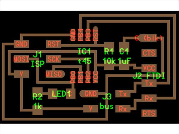
Eagle Bridge Board
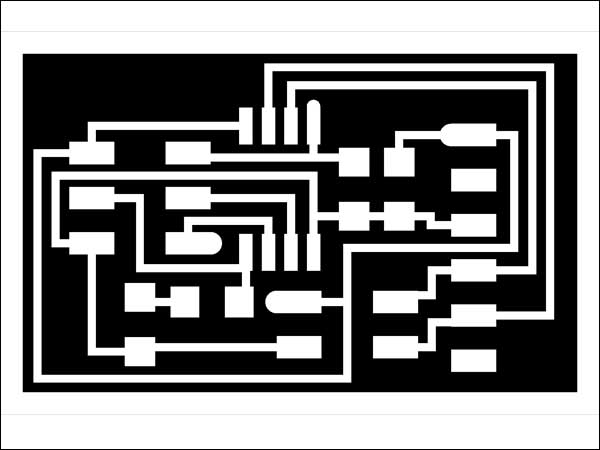
Traces Bridge Board
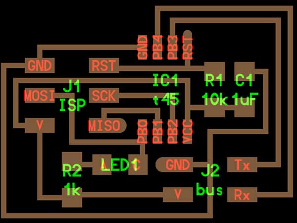
Eagle Node Board
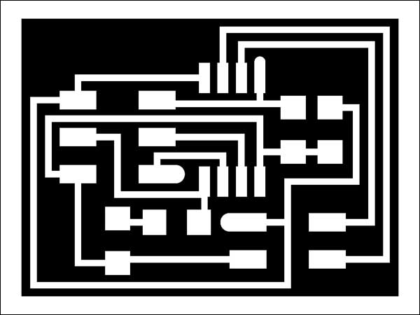
Traces Node Board
Second Phase: Code & Flashing.
Each board must be programmed individually, so it's needful modify the C code for each board.
Each node needs to have a different node ID number (0, 1, 2, 3, etc). The "bridge" board is also a "node".
Then I have done the following steps:
- I downloaded and Copy on Ubuntu Desktop the "bus_fixed" folder from The Tutorial of Providence. page.
- To programm the Bridge I opened the C code file and I put 0 on "#define node_id '#'".
- I connected the bridge board to computer with the FTDI header and I programmed it using the FabISP and, in root modality, I flashed the bridge board as node 0: "sudo make -f hello.bus.45.make program-usbtiny".
- Then I modified the C code and changed the node ID to 1:#define node_id '1' and I saved the file.I repeated the same steps for the other Node. Be careful to define before 1 and after 2 for nodes in "#define node_id '#'
- I used the bridge board to power node boards and connect them to TX and RX. Then I flashed the node board as Node 1: "sudo make -f hello.bus.45.make program-usbtin".
- Same passages shoul be repeated for Node 2
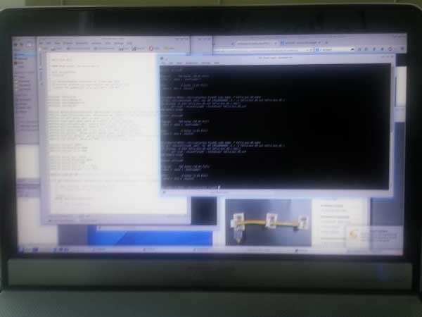
Programming the Boards
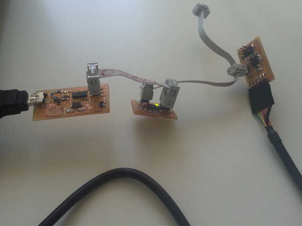
Make the Connection
Third Phase: Serial Communication
After flashing boards with nodes number (1,2,3) I connected the boards with FTDI cable to test my serial bus and then plugged the bridge into the computer.
I Connected the nodes with 4 pin header (Tx,Rx,Vcc,Gnd).
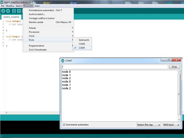
Then I opened the serial monitor in the Arduino Ide setting on 9600 baud in order to communicate all my boards.
Everytime I type a number between 0,1,2 and press enter, there is a general blink in all the boards'Led (is the proof of a first step of information).
Then there is the blink of the Node I have chosen (in response to the number that I typed).The node name (node 0, node1, node2) also was displayed on the serial monitor.
Since the blink was fast I changed in the Code the delay from 100ms to 1000ms.
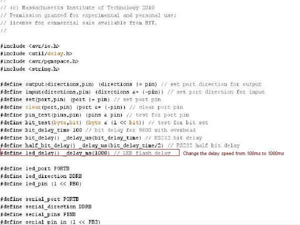
The hello.bus.45.c
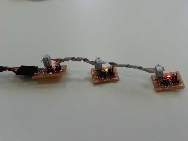
General Blink of all connected Boards