Week11 - Output Devices
Add an output device to a microcontroller board you've designed and program it to do something.
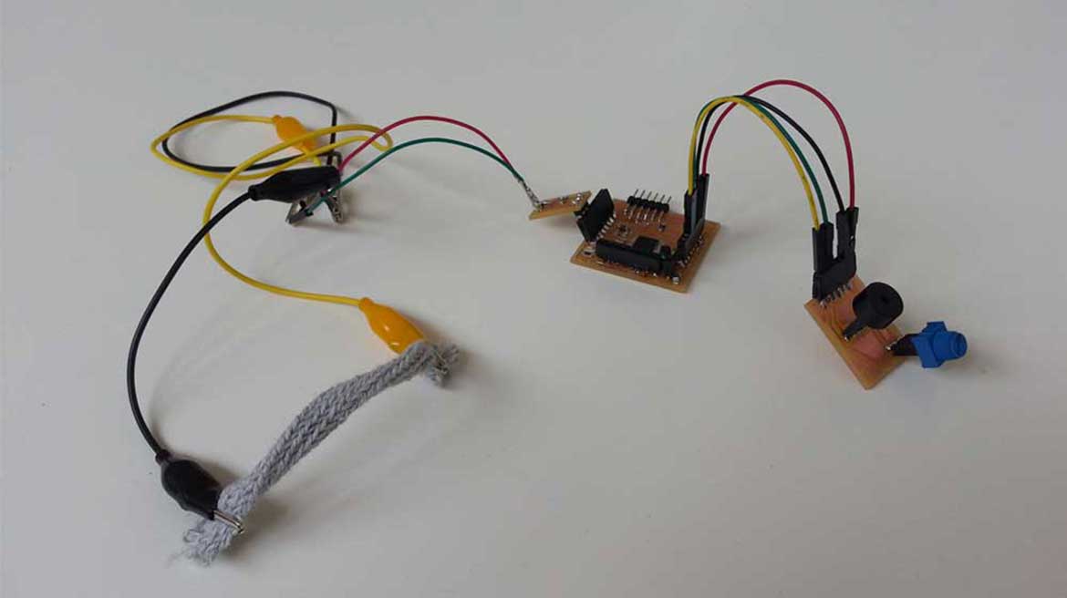
On this week it was requested to add an output device to a microcontroller board we designed and program it to do something. I decided to use this assignment to test a sound output useful for my final project. The idea is to obtain a sound that origins from a motion through the stretching of a cloth. To generate my output it's enough to me an Audio Transducer (piezo) to which I add a Potentiometer to adjust the frequency.
CLASS WEB PAGE:
http://academy.cba.mit.edu/classes/output_devices/index.html
DOWNLOAD FILES:
EAGLE
| PNG
| IDE
REFERENCES:
'Piezo'
'Potentiometer'
'Arduino Tone Tutorial'
First Phase: Shield Design .
To design my output shield I have to think which components I need to put in it. They are definitely a Potentiometer and a Piezo. Precaution, I chose not to solder directly the components on the shield but I preferred put on it the respective female header and connect them when I need it. To draw the board I used again Eagle Software and Photoshop for png files to generate the rml files to send on the milling machine.
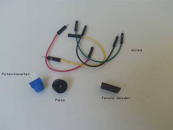
Components that I need on my Output Shield
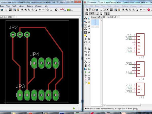
Shield design with Eagle software
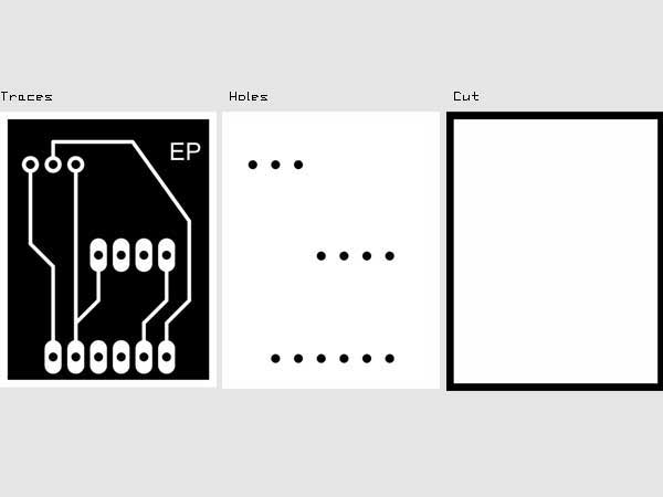
RML Files preparation for Milling Machine
RML Files preparation for Milling Machine
Second Phase: Milling & Soldering.
The process to mill the shield is already know. I imported the png files on fabmodules to prepare the rml files. As the Fabkit Board I had trhee files to put in the Machine: one for the traces with 1/64 tip and the holes and interior files with 1/32 tip. Once milled the shield I went to solder the headers.
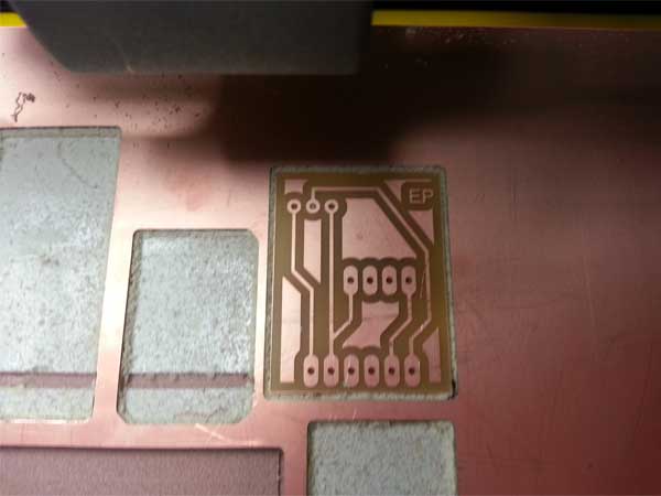
The Shield was milled correctly!
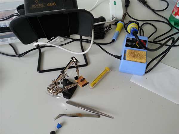
Soldering step was really quickly!
Third Phase: Sketch & Output.
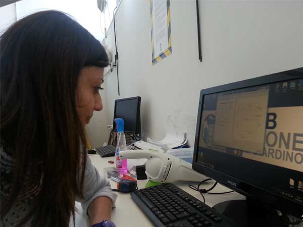
Before programming the sound output on my shield, I needed to understand the working of my circuit with the help of Arduino Board. Searching an example with both the piezo and potentiometerI found several example that use the 'ARDUINO TONE LIBRARY'. After doing a test with Arduino I used my Fabkit and Output Device to reproduce the same thing. On the pinout of 'Atmega 328' I verified the correspondence of the pins to use.
I programmed the microcontroller board with a simple sketch: a loop of alternate rotations in opposite directions and breaks. I controlled the speed using the PWM pin. IDE Arduino Sketch:
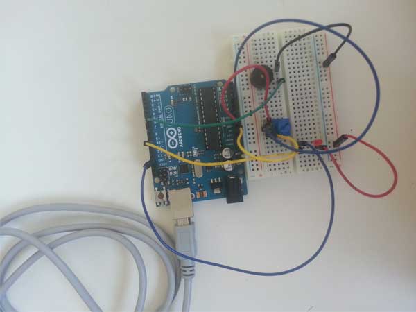
The circuit of my Output on Arduino Board
While I was reproducing the output with my Shield, I had some problems with my Fabkit. With the help of a tutor I checked again my Fabkit and I verified that all was ok. So the conclusion is that Arduino Ide not always read my board.
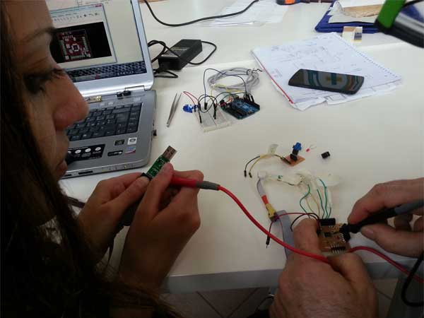
Checking the Fabkit...
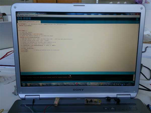
Writing the Sketch for my Output Device.
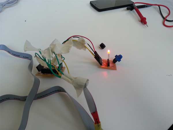
A test with a Red Led.
WHAT I LEARNED:
Theese last weeks were really intense for me because I'm a beginner in Eletronics and Arduino Ide, so I spent a lot of time trying to understand principles and practices that for many people be simple. Step by step I'm learning several concepts and I'm really satisfied!