Networking and communications
The purpose of the week is to fabricate the "hello" network example boards and program them
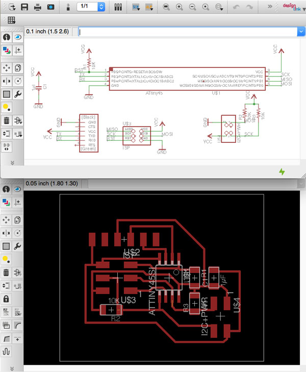
In link with my project i decided to add two board that can detect proximity or vibration .Bridge Board
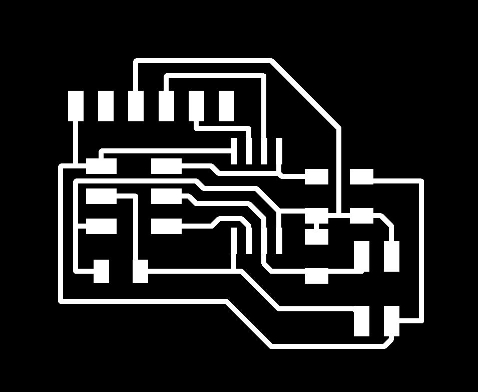
I rebuild this board from Neil's schematic:

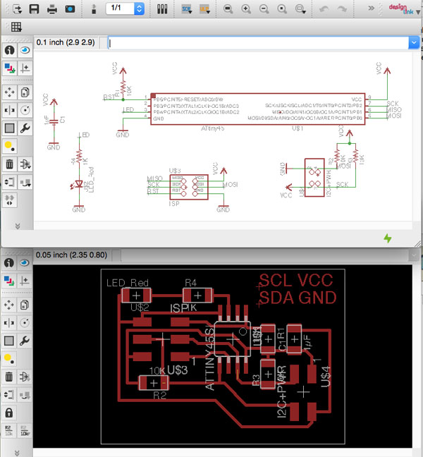
Node LED Board
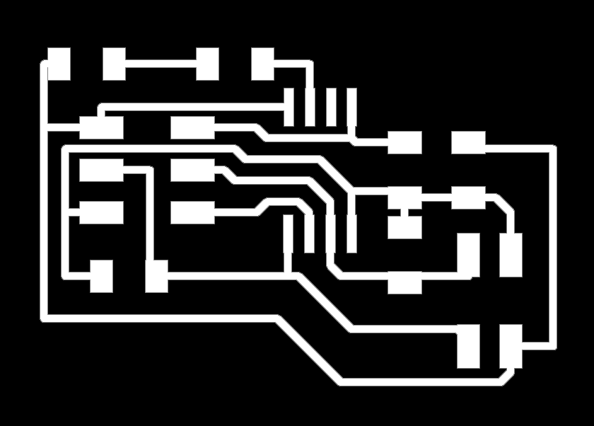
I rebuild this board from Neil's schematic:

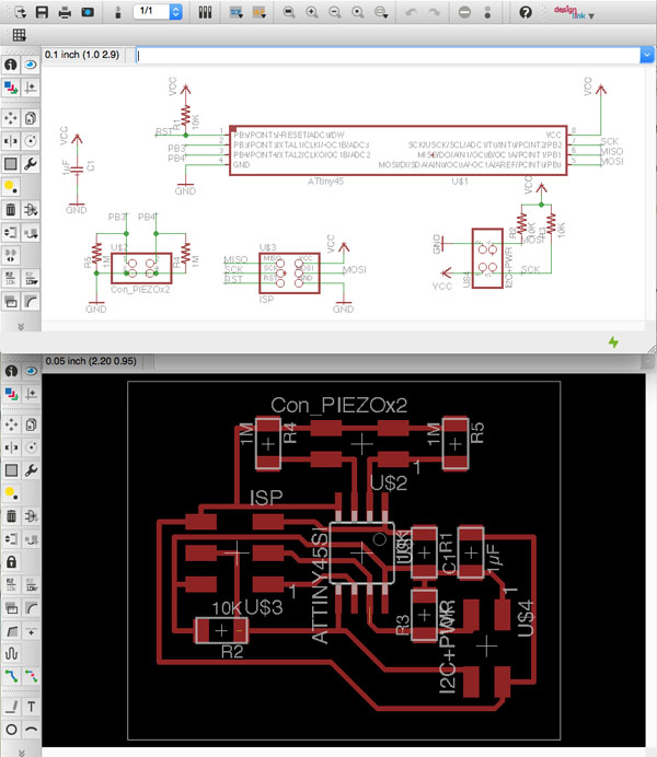
Node IR proximity detection
I would like to detect proximity, I used the Neil's synchronous detection spread spectrum board but I need to detect proximity also on holds that are light off, so I can't use normal led. So based on the same schematic I replace the Led and the phototransistor by ones who work in Infrared spectrum. These 2 componants won't be directly on the board but replaced by a 2x2 PIN connector. The lED and the PhotoTransistor will be put inside the hold.
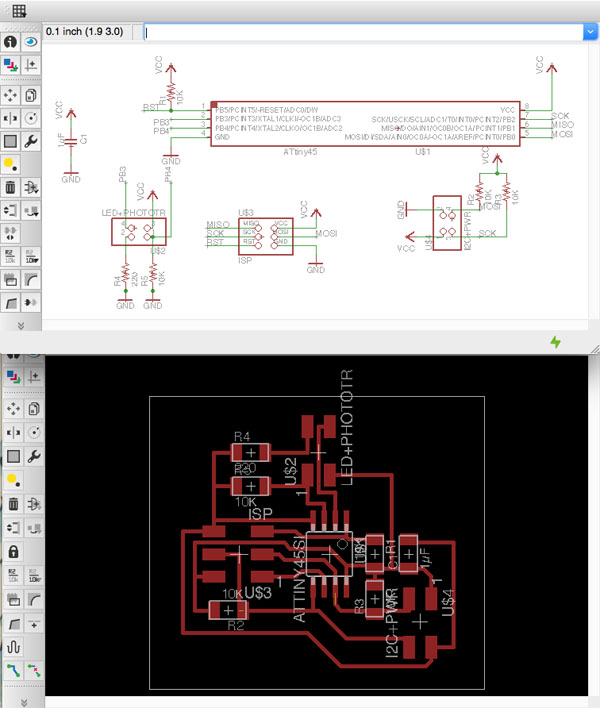

Node Vibration board
I would like to detect vibration when some touch the hold, I decide tu use Piezo disk which transform vibration into electricity. As there is 2 Pin free I will connect 2 piezo by Tiny 45. Same as the other board, these 2 piezo won't be directly on the board but replaced by a 2x2 PIN connector. The piezo will be put on the backside of the hold.

Network test
As I want to use the IDE envirronment, the I2C network for Tiny45 is not in the core lib so you will have to install the following library:
TinyWireS.h for the slave, TinyWireM.h for the master.
According to Arduino.cc,dy default the I2C master library (TinyWireM) is set to run at 1MHz. To run at 8MHz, #defines in USI_TWI_Master.h / .cpp must be changed. No changes are necessary for the I2C slave library (TinyWireS). I have made the following changes in USI_TWI_Master.cpp:
#define F_CPU 8000000UL // was 1000000UL
I have made the following changes in USI_TWI_Master.h:
#define SYS_CLK 8000.0 // was 1000.0
#define T2_TWI 1.3 // was 5
#define T4_TWI 0.6 // was 4
But it was not working, Node slave blink 0ne times at power up but no communications between slaves and master. The Value for T2_TWI and T4_tWI have to be define using an oscilloscope I think. The fablab doesn't have an oscilloscope So I decided to use JMDuino board as master in order to use the Wire library instead of TinyWireM lib.
TinyWireS.h for the slave, TinyWireM.h for the master.
you can find those library
github repository :![]()
Code for Nodes
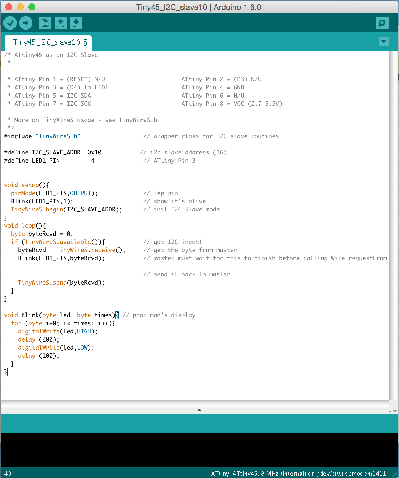
/* ATtiny45 as an I2C Slave
 *

 * ATtiny Pin 1 = (RESET) N/U                      ATtiny Pin 2 = (D3) N/U
 * ATtiny Pin 3 = (D4) to LED1                     ATtiny Pin 4 = GND
 * ATtiny Pin 5 = I2C SDA                          ATtiny Pin 6 = N/U
 * ATtiny Pin 7 = I2C SCK                          ATtiny Pin 8 = VCC (2.7-5.5V)

 * More on TinyWireS usage - see TinyWireS.h
 */
#include "TinyWireS.h"                  // wrapper class for I2C slave routines

#define I2C_SLAVE_ADDR  0x10           // i2c slave address (16) ( 0x11 and 0x12 for the 2 others )
#define LED1_PIN         4              // ATtiny Pin 3


void setup(){
  pinMode(LED1_PIN,OUTPUT);             // lep pin
  Blink(LED1_PIN,1);                    // show it's alive
  TinyWireS.begin(I2C_SLAVE_ADDR);      // init I2C Slave mode
}
void loop(){
  byte byteRcvd = 0;
  if (TinyWireS.available()){           // got I2C input!
    byteRcvd = TinyWireS.receive();     // get the byte from master
    Blink(LED1_PIN,byteRcvd);           // master must wait for this to finish before calling Wire.requestFrom

                                        // send it back to master
    TinyWireS.send(byteRcvd);
  }
}

void Blink(byte led, byte times){ // poor man's display
  for (byte i=0; i< times; i++){
    digitalWrite(led,HIGH);
    delay (200);
    digitalWrite(led,LOW);
    delay (100);
  }
}
code for Bridge
/* ATtiny45 as an I2C Master
 * I2C master
 * SETUP:
 * ATtiny Pin 1 = (RESET) N/U                  ATtiny Pin 2 = N/U
 * ATtiny Pin 3 = (D4) N/U                     ATtiny Pin 4 = GND
 * ATtiny Pin 5 = SDA                          ATtiny Pin 6 = N/U
 * ATtiny Pin 7 = SCK                          ATtiny Pin 8 = VCC (2.7-5.5V)
 * NOTE! - It's very important to use pullups on the SDA & SCL lines!

 * TinyWireM USAGE see TinyWireM.h   */

#include                   // I2C Master lib for ATTinys which use USI
#include

#define NODE1_ADDR   0x10        // 7 bit I2C address node1
#define NODE2_ADDR   0x11        // 7 bit I2C address node2
#define NODE3_ADDR   0x12        // 7 bit I2C address node3
#define RX 3
#define TX 4
int datareceived = 0;
SoftwareSerial Myserial(RX,TX);

void setup(){
  Myserial.begin(9600);
  TinyWireM.begin();                    // initialize I2C lib
  delay (1000);
}

void loop(){
  delay(5000);
  Myserial.print("demande de blink node1");
  BlinkNode(NODE1_ADDR,0x1);
  datareceived = TinyWireM.receive();
  Myserial.println(datareceived);
  delay (1000);
  BlinkNode(NODE2_ADDR,0x2);
  delay (1000);
  BlinkNode(NODE3_ADDR,0x3);
  delay (1000);

}

void BlinkNode(byte NodeNum,byte times)
{
  TinyWireM.beginTransmission(NodeNum);
  TinyWireM.send(times);                 // Ask node to blink n time
  TinyWireM.endTransmission();          // Send to the slave
}
According to Arduino.cc,dy default the I2C master library (TinyWireM) is set to run at 1MHz. To run at 8MHz, #defines in USI_TWI_Master.h / .cpp must be changed. No changes are necessary for the I2C slave library (TinyWireS). I have made the following changes in USI_TWI_Master.cpp:
#define F_CPU 8000000UL // was 1000000UL
I have made the following changes in USI_TWI_Master.h:
#define SYS_CLK 8000.0 // was 1000.0
#define T2_TWI 1.3 // was 5
#define T4_TWI 0.6 // was 4
But it was not working, Node slave blink 0ne times at power up but no communications between slaves and master. The Value for T2_TWI and T4_tWI have to be define using an oscilloscope I think. The fablab doesn't have an oscilloscope So I decided to use JMDuino board as master in order to use the Wire library instead of TinyWireM lib.
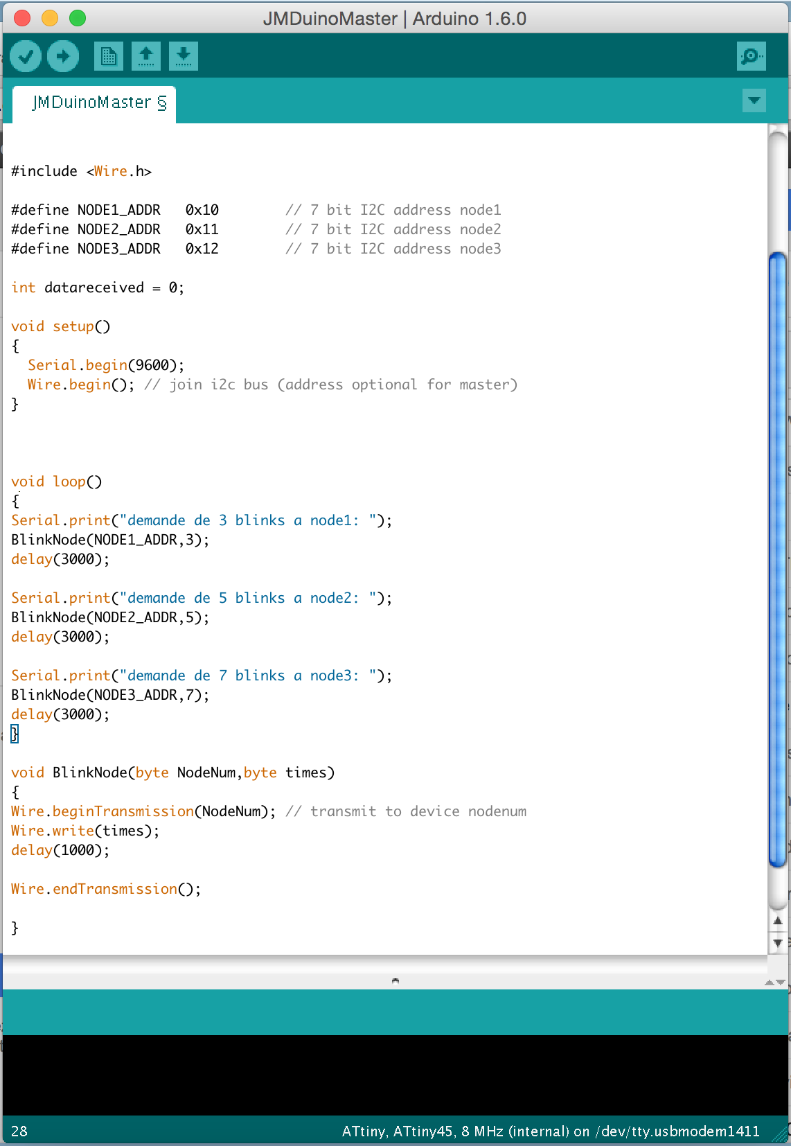
// Wire Master Writer // Refer to the "Wire Slave Receiver" #include#define NODE1_ADDR 0x10 // 7 bit I2C address node1 #define NODE2_ADDR 0x11 // 7 bit I2C address node2 #define NODE3_ADDR 0x12 // 7 bit I2C address node3 int datareceived = 0; void setup() { Serial.begin(9600); Wire.begin(); // join i2c bus (address optional for master) } void loop() { Serial.print("demande de 3 blinks a node1: "); BlinkNode(NODE1_ADDR,3); delay(3000); Serial.print("demande de 5 blinks a node2: "); BlinkNode(NODE2_ADDR,5); delay(3000); Serial.print("demande de 7 blinks a node3: "); BlinkNode(NODE3_ADDR,7); delay(3000); } void BlinkNode(byte NodeNum,byte times) { Wire.beginTransmission(NodeNum); // transmit to device nodenum Wire.write(times); delay(1000); //Wire.requestFrom(NodeNum,2); //while (Wire.available()) // slave may send less than requested // { //datareceived = Wire.read(); //Serial.print("reponse:"); //Serial.println(datareceived); // } Wire.endTransmission(); }
Apparently it works but some loops after in the master program it seems that the synchronisation is lost. The debugging using serial.print doesn't help a lot. Without an oscilloscope I was not able to find the problem.
you can find the design files on my
github repository :![]()