Output Devices
Week11 - Apr 15 Output devices
WS2812B Technology
For This week we had to create a board and managing any kind of output. I decided to focus on my project "interactive climbing holds" . to light up my holds I will need 1,2 or 3 RGB leds by hold depending of the size of it. If we talk about 50 holds, I will have to manage more than 100 Leds, so for managing them without huge cabling and limiting the number of pin, I decided to use a led strip with WS2812B which is an intelligent control LED light source that the control circuit and RGB chip are integrated in a package. It's a 4 Pin componant (GND VCC Din Dout). you can cascade them :data outputs from each chip when the previous data overflows the chip buffer. The Chip/LED position in the chain determine the LED Address.Before the technology (WS2801) use SPI which require a clock line) now they using NZR which don’t require a clock line but relay on more strict timings of the data.the Data Transmission rate is about 400Kbps with an operation frequecy about 800KHz. It uses 24bits data frame:G7 G6 G5 G4 G3 G2 G1 G0 R7 R6 R5 R4 R3 R2 R1 R0 B7 B6 B5 B$ B3 B2 B1 B0
You can find more information by reading the datasheet :
It could be interesting to create the framing code by myself but unfortunatly the Fablab doesn't have an oscilloscope so I will be impossible to tune and debug. And honestly I running out of time.
But as it exist many open source softare library for Arduino and Teensy I will use Adafruit_NeoPixel
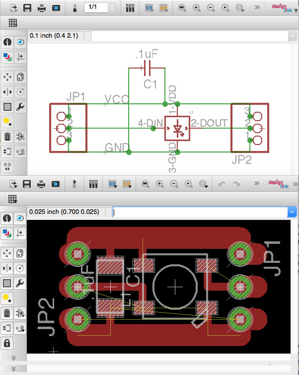
WS2812B Breakout
I first create a breakout for only one Led but keeping in mind to developpe the BRD file to be able to cascade the easilly.note: the ws2812b is part of the Adafruit library for Eagle.

Then As the board is cascadable I just use Photoshop to create a bigger one (5 LEDs)


ADD pict and code sample
New Breakout for ClimbingHolds .. Project
I create another Breakout to be include directly under the hold at casting time: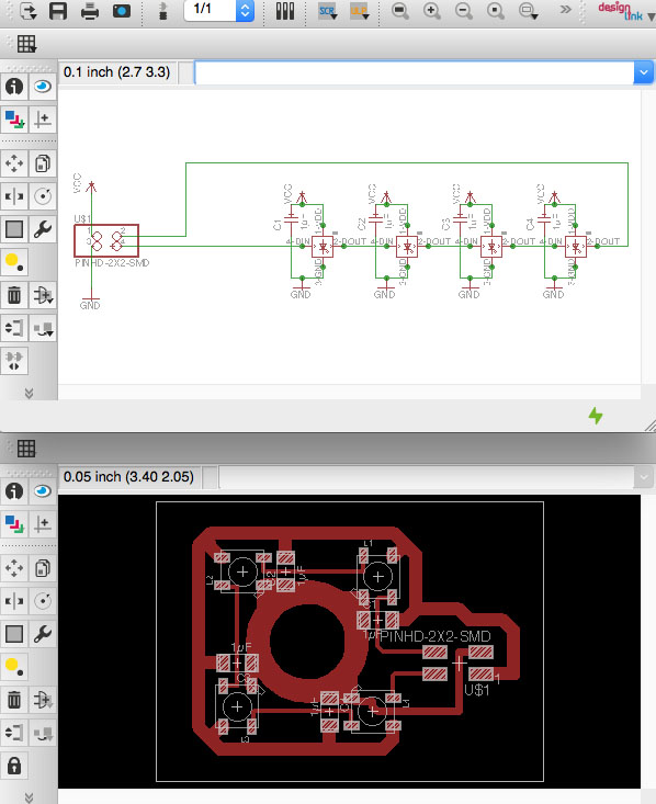
 As those breakouts are cascadable it's important to think about the power used by the Leds when you design the trace.
It exist LEDstrip with more than 60 LEDs they are also cascadable but you have think that for 60 LEDs the current in the circuit will be more than 5 A and if your traces are too small they will burn. by change the WS2812b led strip is normally equipped with power at beginning and at the of the strip, that means you can add a power line every 60 Leds.
Some other interesting features are:
- Intelligent reverse connect protection, the power supply reverse connection does not damage the IC.
- Built-in electric reset circuit and power lost reset circuit.
- Any two point the distance more than 5m transmission signal without any increase circuit.
- When the refresh rate is 30fps, cascade number are not less than 1024 points.
I think WS2812b is really intersting technology and should be added in the fablab componants list.
you can find all the eagle files and png file on my
github repository :![]()
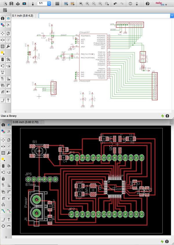
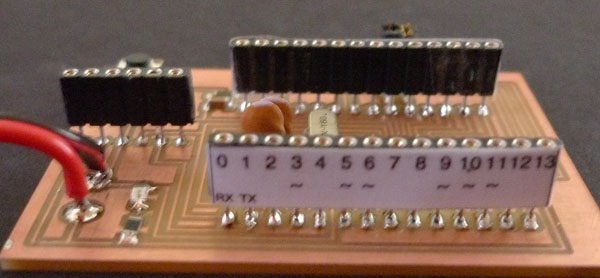
JMDuino Board
As it's not permit to use Prefabricate Arduino Board I decided to developpe my Own Arduino Style Board. What I want :-A fully compatible Arduino Board. I will use a ATmega328P with External 16MHz osc.
-ISP and FTDI connector won't on the the Board but on an easyplug Shield.
-A separated connector for the Bluetooth HC-06 breakout.
-Ready SCL,SDA (A4,A5) line with 10k pull up resistor on the board with jumper to activate them.
-One LED for Power and Reset Button.
-2x14Pins connector: 0..13 for digital pin, A0..A7 2xGND 2xVCC Reset DTR(just for FTDI on shield)

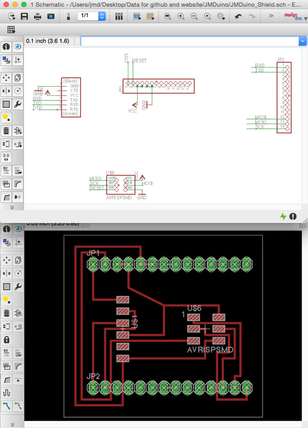
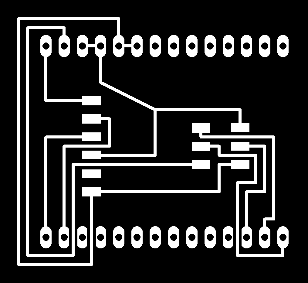
JMDuino Shield (ISP + FTDI)


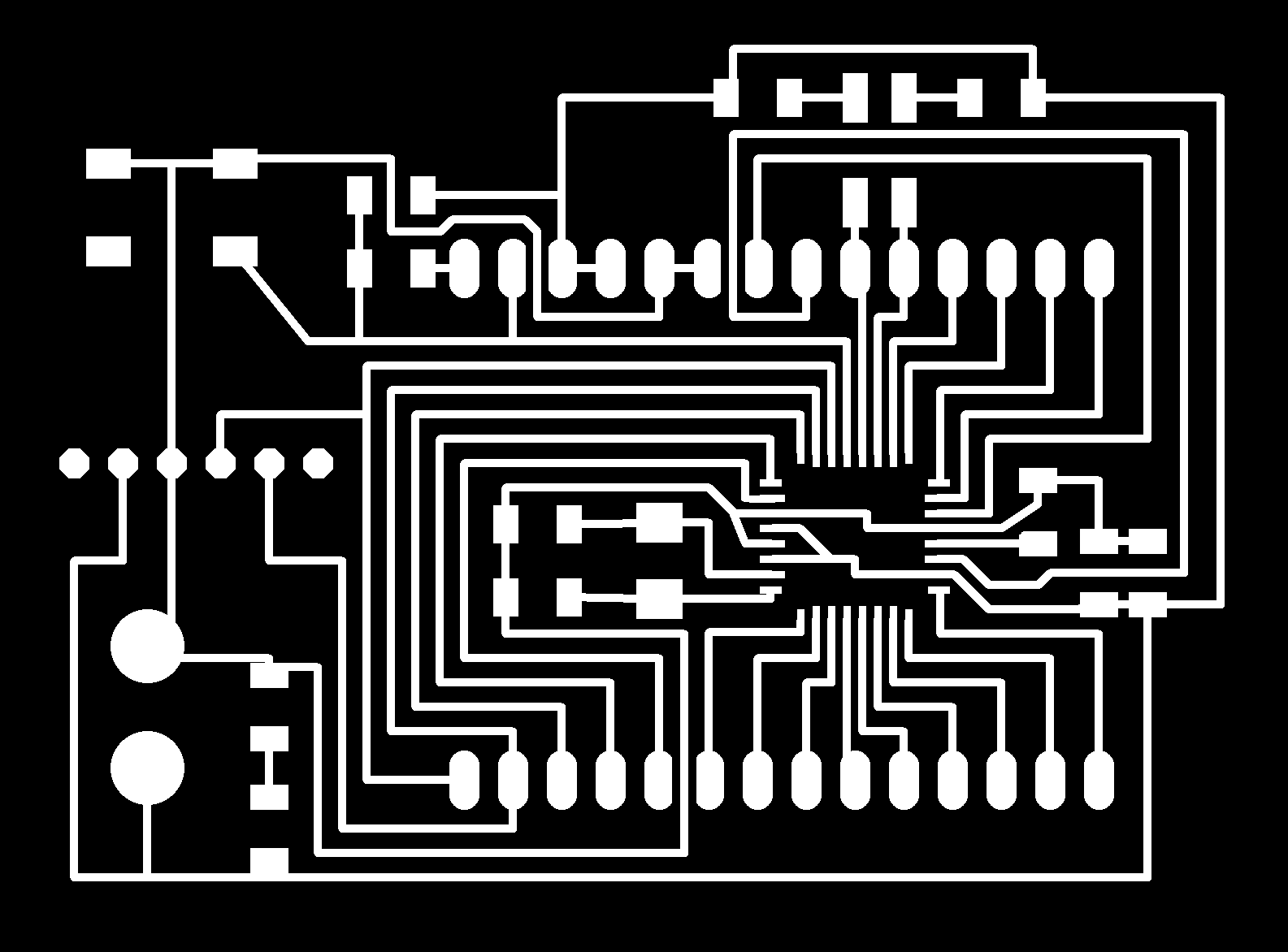
Milling PCB adventures
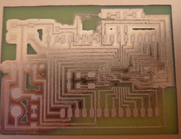
The Milling tool I used ( 0.3 mm )is very fragile so I always use a cut depth of 0.05mm with a speed of 2 mm/s. the problem is that sometime the cut depth is not enough to remove the copper, then you have to redo the job with cut depth from -0.05 to -0.1.
My error was to put -1 to get ride of all the unecessary copper (1.5 hour and unfortunatly I have to run the job again (1.5 hour again), during the second pass. After 40 min, it happends a big power cut in the neighborhood. So I have to restart again. I don't know if I had a malediction but after 10min the milling tool die...
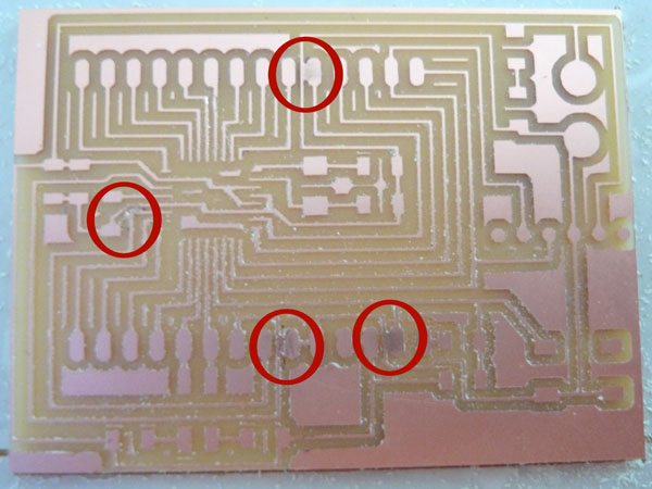
Then I asked if it was possible to stay in fablab after its closure to redo my PCB milling. I have to use the new Milling tools that Jean-Michel (My Guru) brought a week ago. I have to change the Spinhead to fit with the new diameter.I decided to change the -1 parameter to 4 to save time. and I change the diameter of the milling tools: 1/64 --> 0.4mm. and restart a new job.
After 1 hour and 20min The PCB was done but because I change from 0.3mm to 0.4 mm without checking the toolpath the result was not so good:
At this time (~8pm) I was very frustraded and I decided to back home (1h30 of train) thinking that I will fix the problem with cutter.
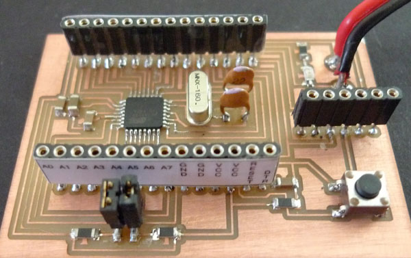
The cutter doesn't permit to fix the problem as I destroyed two lines. so I decided to come on Saturday afternoon to redo the job again with the last 0.3mm tool I kept at home. To ensure to do not have the problem again I modified a part trace directly under Photoshop.I replace the Spinhead, put 0.3 mm endmill, check the tool path and restart the job.
Two hours after (including Soldering):
Note: the fablab doesn't have 16Mhz Oscillator and 22pF so I went to an electronic shop in town get them but unfortunatly they didn't have them in surface package, so I took them in DIP version.
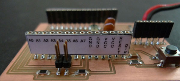
nice with stickers !!!
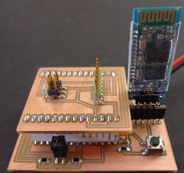
With its shield (ISP+FTDI) and Bluetooth BreakOut
bootloader and Test program
As it's fully compatible with Arduino UNO Burning the bootloader was very simple:-Put the shield.
-Connect FTDI for the power
-Connect the ISP.
-Start Arduino IDE. select Arduino Uno and the programer Then Burn the bootloder.
That's it!!!
To program it you just have to plug the FTDI cable and its port then program it as an Arduino UNO.
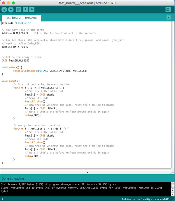
I decided to test My JMDuino as well as the 2 Breakouts at the same time. So i have to download FastLED
#include "FastLED.h"

// How many leds in the strip
#define NUM_LEDS 9    /*4 in the 1st breakout + 5 in the second*/

// For led chips like Neopixels, which have a data line, ground, and power, you just
// need to define DATA_PIN.
#define DATA_PIN 6


// Define the array of leds
CRGB leds[NUM_LEDS];

void setup() {
	FastLED.addLeds(leds, NUM_LEDS);
}

void loop() {
	// First slide the led in one direction
	for(int i = 0; i < NUM_LEDS; i++) {
		// Set the i'th led to red
		leds[i] = CRGB::Red;
		// Show the leds
		FastLED.show();
		// now that we've shown the leds, reset the i'th led to black
		leds[i] = CRGB::Black;
		// Wait a little bit before we loop around and do it again
		delay(300);
	}

	// Now go in the other direction.
	for(int i = NUM_LEDS-1; i >= 0; i--) {
		// Set the i'th led to red
		leds[i] = CRGB::Red;
		// Show the leds
		FastLED.show();
		// now that we've shown the leds, reset the i'th led to black
		leds[i] = CRGB::Black;
		// Wait a little bit before we loop around and do it again
		delay(300);
	}
}
Uploading the software using Arduino IDE:
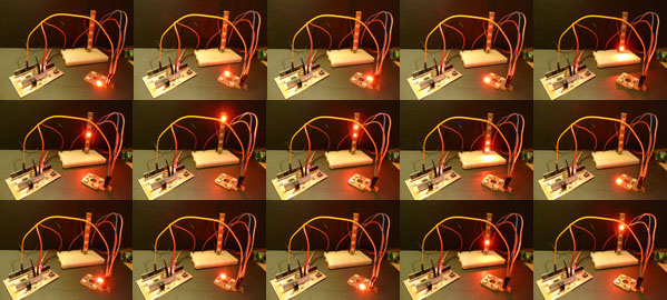
Victory It's working fine:
you can find all the eagle files and png file and progam files on my
github repository :![]()