****************************************************************************************************************
ASSIGNMENT: ADD A SENSOR TO A MICROCONTROLLER BOARD THAT YOU'VE DESIGNED AND READ IT
PROJECT: EXERCISE N°6 OF ARDUINO PROJECT BOOK - LIGHT THEREMIN -
INPUT SENSOR: PHOTORESISTOR
SOFT: IDE ARDUINO 1.6.3BOARD: SATSHAKIT BY --> DANIELE INGRASSIA // GIT HUB REPOSITORY OF THE PROJECT
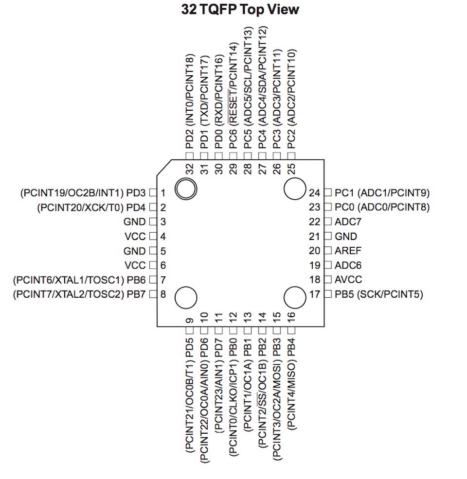
DATASHEET: MICROCONTROLLER ATMEGA 328P DATASHEET
NOTE: MY FIRST ARDUINO PROJECT EVER :-)
DOWNLOAD:
****************************************************************************************************************
1ST PART --> MAKE A HOMEMADE ARDUINO
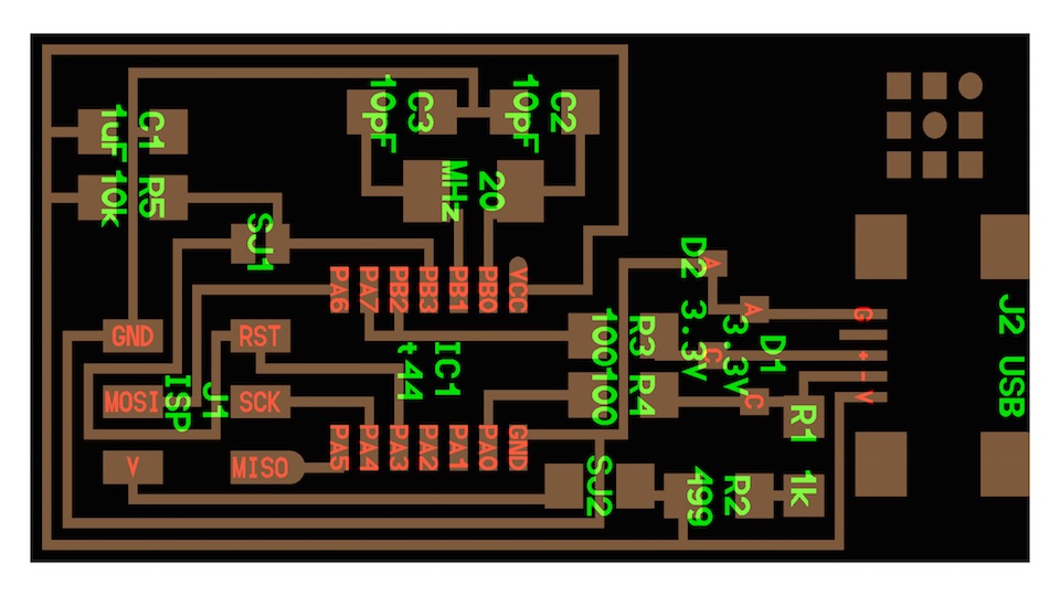
To produce my board design, I used the project by Daniel Ingrassia of my Fab Academy Class.
What I did :
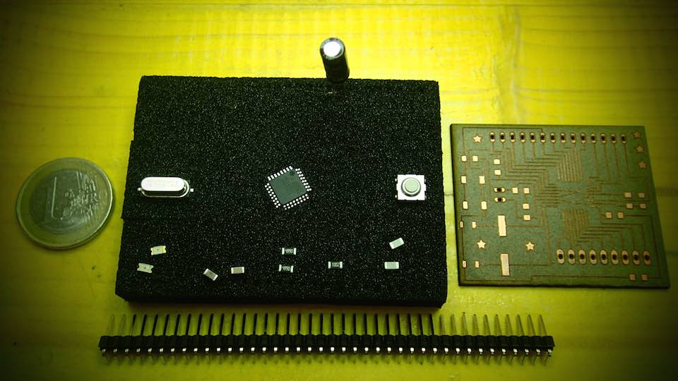
1--> I lasered and engraved the board according to my experiences in WEEK 4 et WEEK 6
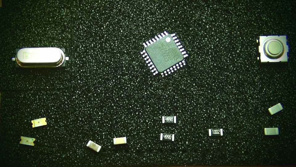
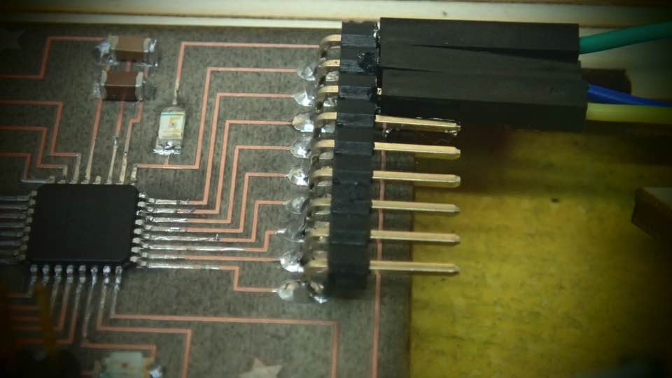
2--> I soldered the components according to the scheme
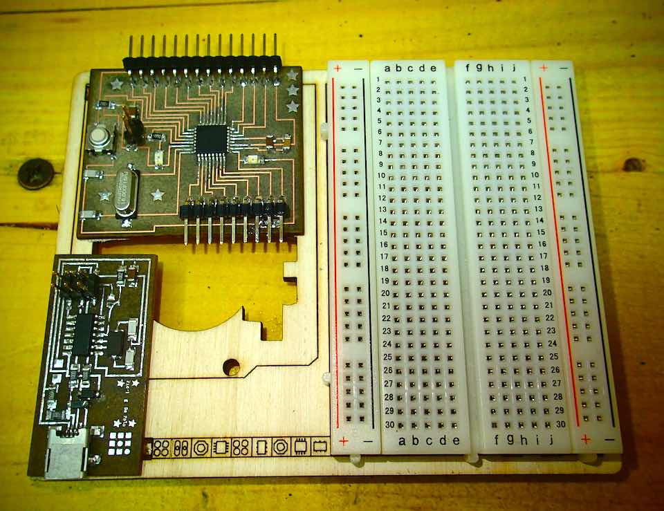
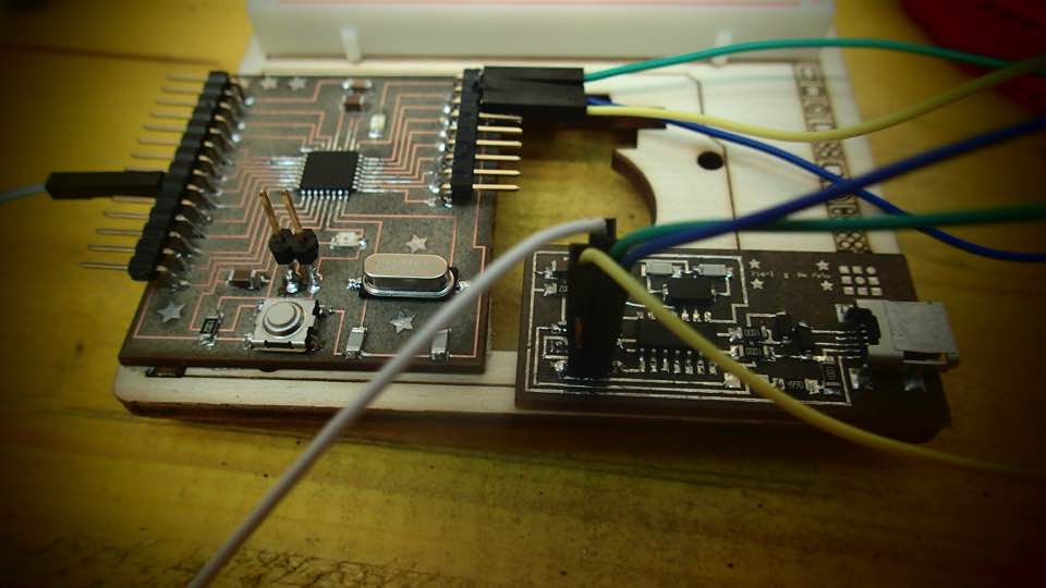
2ND PART --> CONNECT FAB ISP TO THE SATSHAKIT MICROCONTROLLER FOR PROGRAMMING IT
When the board was ready I followed this process to program it :
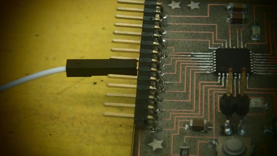
I connected this pin list, I kooked at the FabISP Labeled Board reference and the Satsha Kit Pin
Mapping :
MOSI (Master Output Slave Input) in Fab ISP to --> board pin 11
MISO (Master Input Slave Output) in Fab ISP to --> board pin 12
SCK (Serial Clock) in Fab ISP to --> board pin 13
RST (Reset ) in Fab ISP to --> board pin RST
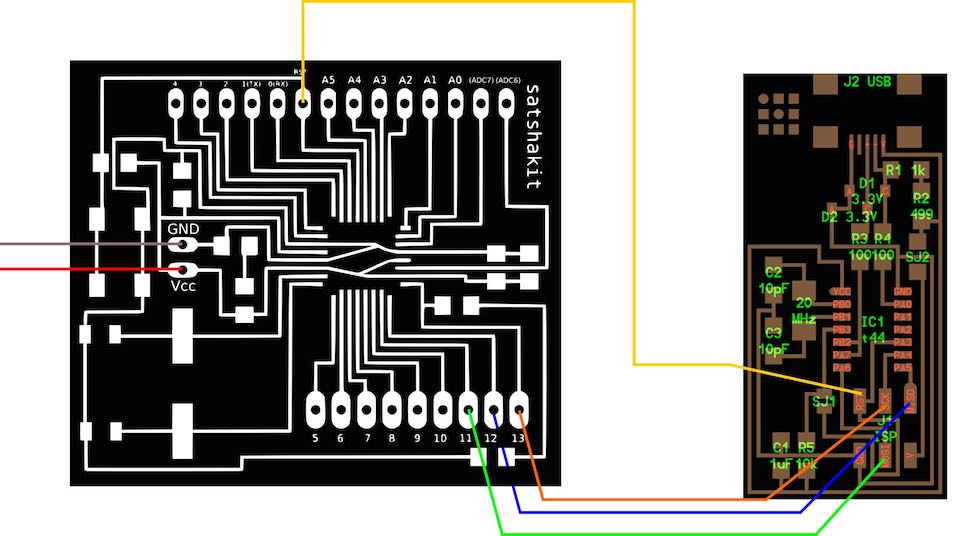
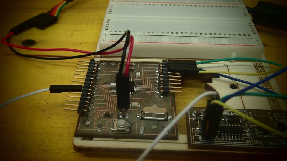
Connect the FTDI (Future Technology Devices International) cable with red (+) and black (-) pins, to the Fab Kit according to the map
(FIRST connect the USB cable between the Fab ISP and computer; SECOND connect the Fab Kit with the FTDI cable to the computer)
Now the 2 boards are powered and we are ready to upload Bootloader.
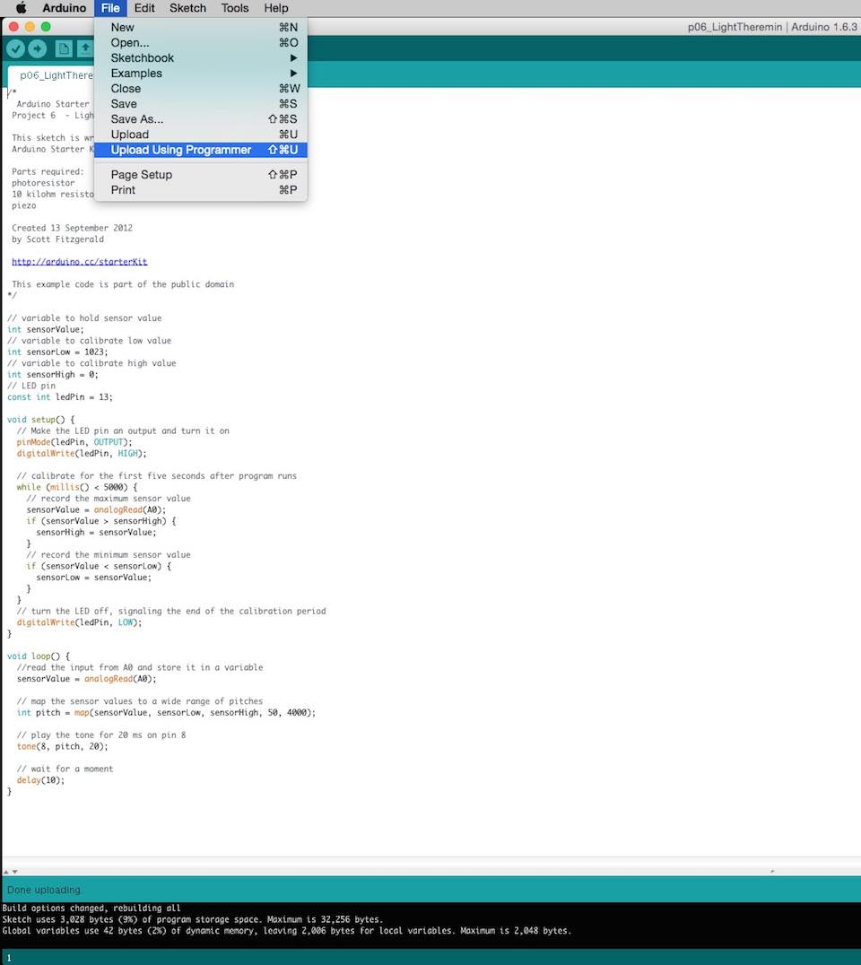
3RD PART--> LOAD BOOTLOADER WITH IDE ARDUINO 1.6.3
Follow the subsequent images settings:
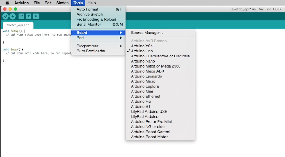
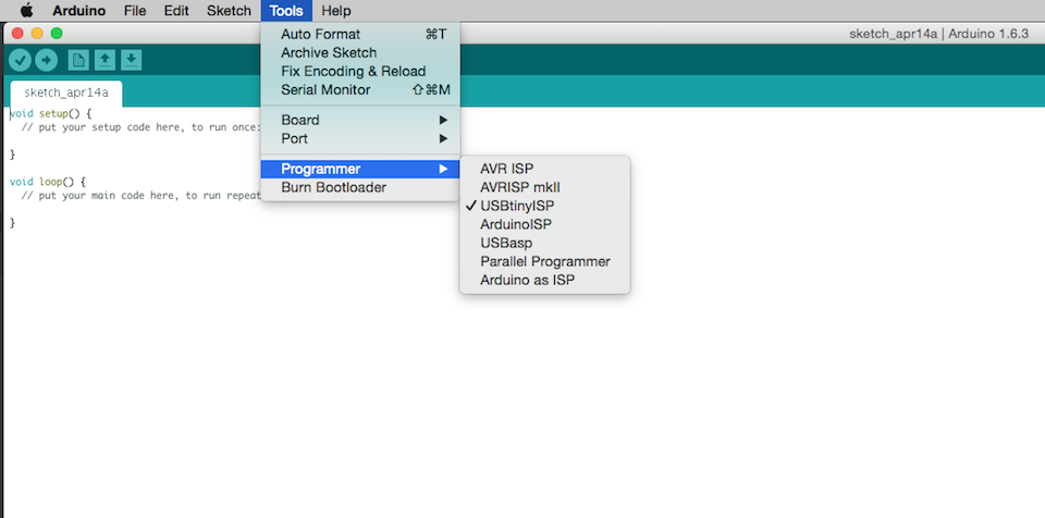
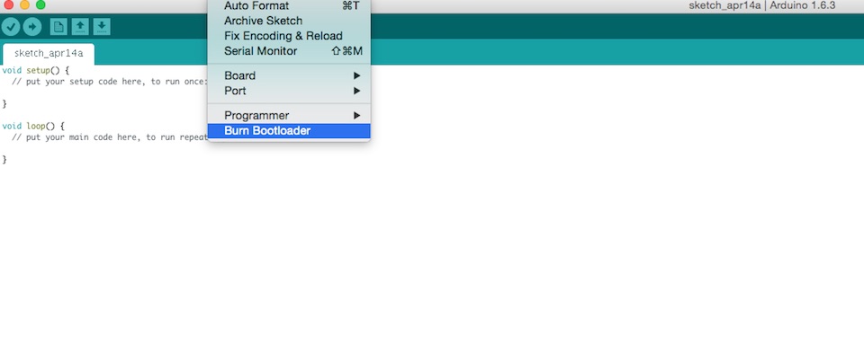
DONE BURNING !!! Now the board has the Bootloader :-)
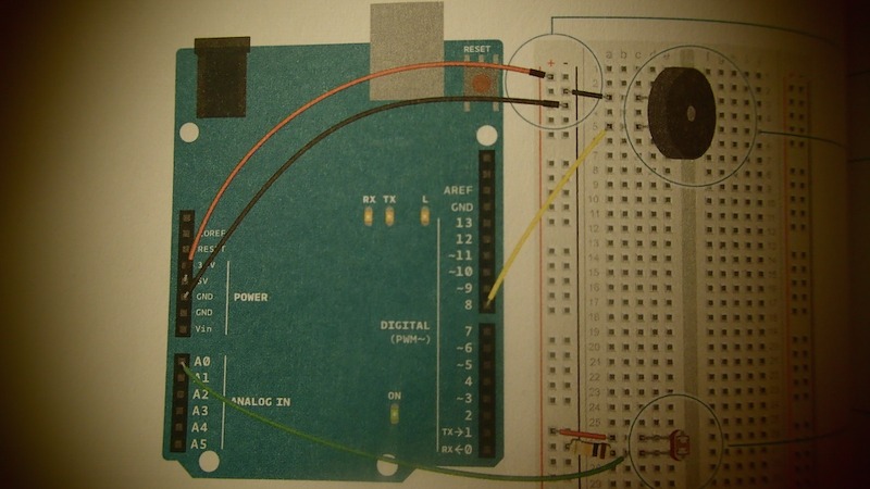
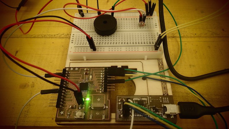
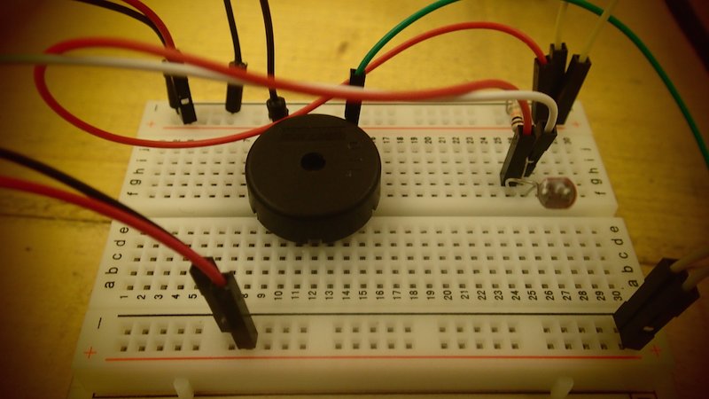
4TH PART -->BUILD THE CIRCUIT FOR A LIGHT THEREMIN
Elements : 1 Piezo // 10 Kilohm Resistor // 1 Photoresistor
I connected the pin A0 of SATSHAKIT to the ground of Photoresistor with the 10k Resistor
I connected the pin 8 of SATSHAKIT to the Piezo
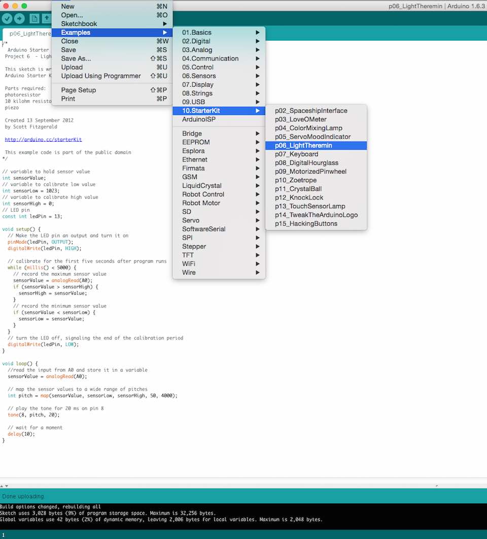
5TH PART --> THE CODE
In reality, I did not change anything of this sketch. I just read it and understand that:
I understand how to connect a Photoresistor and the importance of 10k resistor for make it work properly
How to menage the analog input of the microcontroller
How to use it into the code, for genereting sound by converting that into pwm value
I also understand the function "TONE" for generate different frequences
	/*
  Arduino Starter Kit example
 Project 6  - Light Theremin

 - Read and Studied by Pierluigi De Palo - For the Fab Academy 2015 Exercise "INPUT DEVOICE"

 This sketch is written to accompany Project 6 in the
 Arduino Starter Kit

 Parts required:
 photoresistor
 10 kilohm resistor
 piezo

 Created 13 September 2012
 by Scott Fitzgerald

 http://arduino.cc/starterKit

 This example code is part of the public domain
*/

// variable to hold sensor value
int sensorValue;
// variable to calibrate low value
int sensorLow = 1023;
// variable to calibrate high value
int sensorHigh = 0;
// LED pin
const int ledPin = 13;

void setup() {
  // Make the LED pin an output and turn it on
  pinMode(ledPin, OUTPUT);
  digitalWrite(ledPin, HIGH);

  // calibrate for the first five seconds after program runs
  while (millis() < 5000) {
    // record the maximum sensor value
    sensorValue = analogRead(A0);
    if (sensorValue > sensorHigh) {
      sensorHigh = sensorValue;
    }
    // record the minimum sensor value
    if (sensorValue < sensorLow) {
      sensorLow = sensorValue;
    }
  }
  // turn the LED off, signaling the end of the calibration period
  digitalWrite(ledPin, LOW);
}

void loop() {
  //read the input from A0 and store it in a variable
  sensorValue = analogRead(A0);

  // map the sensor values to a wide range of pitches
  int pitch = map(sensorValue, sensorLow, sensorHigh, 50, 4000);

  // play the tone for 20 ms on pin 8
  tone(8, pitch, 20);

  // wait for a moment
  delay(10);
}