For the week 7, we have to program the board to do something, with as many different programming languages and programming environments as possible.
First Approach
First, given my lack of experience in programming, I downloaded a program already compiled (written in C) to begin to understand how it is structured and also to see if my board was working.
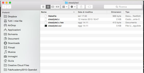
In the program folder that I downloaded are two files: the Makefile, which is used to automate the programming, and the file steadyled.c which is the program.
#include <avr/io.h>
#include <inttypes.h>
#include <util/delay.h>
void delay_ms(uint16_t ms);
void init_io();
int button_is_pressed();
void toggle_led();
#define F_CPU 20000000UL /* 20MHz crystal oscillator */
#define BUTTON_PORT PORTA /* PORTx - register for button output */
#define BUTTON_PIN PINA /* PINx - register for button input */
#define BUTTON_BIT PA3 /* bit for button input/output */
#define LED_PORT PORTA /* PORTx - register for LED output */
#define LED_BIT PA7 /* bit for button input/output */
#define LED_DDR DDRA /* LED data direction register */
#define DEBOUNCE_TIME 25 /* time to wait while "de-bouncing" button */
#define LOCK_INPUT_TIME 250 /* time to wait after a button press */
int
main (void)
{
init_io();
while (1)
{
if (button_is_pressed())
{
toggle_led();
}
}
}
void delay_ms(uint16_t ms) {
while ( ms )
{
_delay_ms(1);
ms--;
}
}
void
init_io()
{
/* set LED pin as digital output */
LED_DDR = _BV (LED_BIT);
/* led is OFF initially (set pin high) */
LED_PORT |= _BV(LED_BIT);
/* turn on internal pull-up resistor for the switch */
BUTTON_PORT |= _BV(BUTTON_BIT);
}
int
button_is_pressed()
{
/* the button is pressed when BUTTON_BIT is clear */
if (bit_is_clear(BUTTON_PIN, BUTTON_BIT))
{
delay_ms(DEBOUNCE_TIME);
if (bit_is_clear(BUTTON_PIN, BUTTON_BIT)) return 1;
}
return 0;
}
void
toggle_led()
{
LED_PORT ^= _BV(LED_BIT);
}
Once downloaded file, I changed the number of pins where are connected the button and the LED (in the file above, pins are already modified) using the button for PA3 and PA7 for Led.
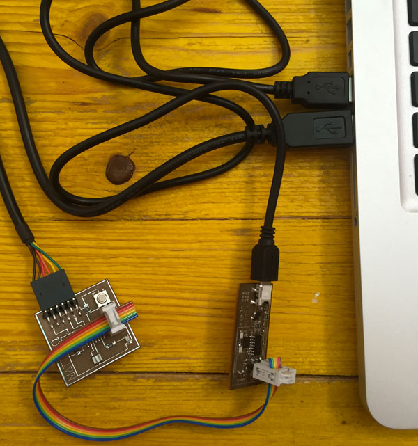
After that, I connected the FabISP and the board to the PC, and connected each other with the rainbow cable.
After connecting the two boards, open the terminal and enter the directory of the program "steadyled":
MacBook-Pro-di-Giulia:~ Giulia$ cd Downloads/steadyled
MacBook-Pro-di-Giulia:steadyled Giulia$
After that, we have to type the command "make" in order to create the excecute the Makefile. The Makefile create by default the hexadecimal file (steadyled.c.hex).
Finally we have to do the "make program-usbtiny" to program the board:
MacBook-Pro-di-Giulia:steadyled Giulia$ sudo make program-usbtiny
avr-objcopy -O ihex steadyled.out steadyled.c.hex;\
avr-size --mcu=attiny44 --format=avr steadyled.out
AVR Memory Usage
----------------
Device: attiny44
Program: 140 bytes (3.4% Full)
(.text + .data + .bootloader)
Data: 0 bytes (0.0% Full)
(.data + .bss + .noinit)
avrdude -p t44 -P usb -c usbtiny -U flash:w:steadyled.c.hex
avrdude: AVR device initialized and ready to accept instructions
Reading | ################################################## | 100% 0.01s
avrdude: Device signature = 0x1e9207
avrdude: NOTE: "flash" memory has been specified, an erase cycle will be performed
To disable this feature, specify the -D option.
avrdude: erasing chip
avrdude: reading input file "steadyled.c.hex"
avrdude: input file steadyled.c.hex auto detected as Intel Hex
avrdude: writing flash (140 bytes):
Writing | ################################################## | 100% 0.26s
avrdude: 140 bytes of flash written
avrdude: verifying flash memory against steadyled.c.hex:
avrdude: load data flash data from input file steadyled.c.hex:
avrdude: input file steadyled.c.hex auto detected as Intel Hex
avrdude: input file steadyled.c.hex contains 140 bytes
avrdude: reading on-chip flash data:
Reading | ################################################## | 100% 0.43s
avrdude: verifying ...
avrdude: 140 bytes of flash verified
avrdude: safemode: Fuses OK (E:FF, H:DF, L:5E)
avrdude done. Thank you.
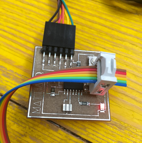
After that, the LED should turn on: this means that the board is working properly and that has been programmed!
This was just an example, useful to see if the board is working properly and to begin to understand how is structured and how work a program written in C.
Now for the assignment of the week i have to study a "little bit" of C languages to write a personal code for my board!