Electronics production
.
The weekly assignment focuses on learn how to use a high precision milling machine to fabricate boards, learn surface mount soldering skills and make a FabISP. Please note that I've not created a new design, so,according to the document: TheFabAcademyHandbook (2015), design files won't be attached.
At the beginning of this assignment I was terrified by soldering ! I’ve never solder in my life and I’m myopic, so ISP production has been considered as a nightmare.
In order to optimize material loss, we used the same original board to produce more that one personal ISP part. All the files used to realize the board have been donwloaded from the assignment page. 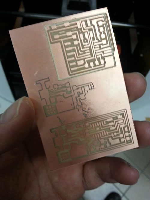
Setting the machine was quite easy. Fab modules are very easy to understand and just a little bit of memory is needed to keep in mind the basics settings. The complex part, for people used not to “touch” machines and tools is to change the 1/32 to 1/64 and back without losing the mentioned parts. Another difficult sensation is to set the Z level, just by moving a piece of paper under the point. The Z setting is very important if you do not want to break the point or loss your board. The most important lesson I’ve learned is to “ear” the work. Bad sound…bad work.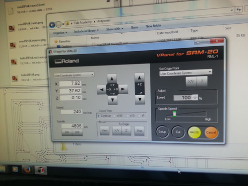
One of my tutor, probably impressed by my dark face, teach me the basics of soldering by fixing two “feet” of the processor but suggesting to find my personal way to reach the final design of the ISP and generally of all the electronic prototypes.”Third hand”…enlargement lens… the story begins.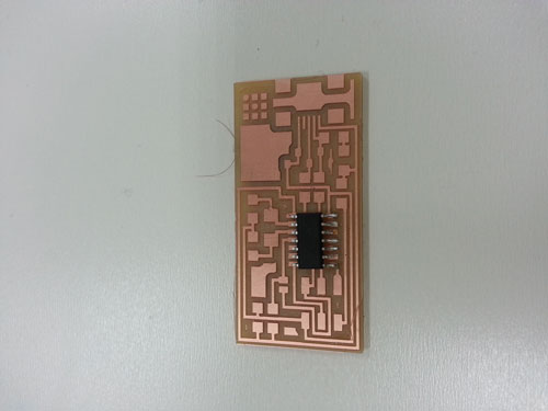
I take note of all the very small components of the ISP: crystal, resistor, capacitor, etc. The BOM (bill of materials) is very complex, because component are very small and they have not enough space to include informations/details, so you have to be very careful in order not lo lose it or confuse it. The component list:
. 1 ATTiny 44 microcontroller
. 1 Capacitor 1uF
. 2 Capacitor 10 pF
. 2 Resistor 100 ohm
. 1 Resistor 499 ohm
. 1 Resistor 1K ohm
. 1 Resistor 10K
. one 6 pin header
. 1 USB connector
. 2 jumpers - 0 ohm resistors
. 1 Cystal 20MHz
. two Zener Diode 3.3 V
. one usb mini cable
. one ribbon cable
. two 6 pin connectors. 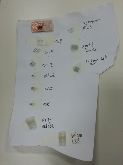
Sometimes it’s very difficult to understand (even with datasheets) the usage of the components. I.e. diods have their own polarity. I’ve learned to find on the web additional informations or tutorial about the mentioned components starting from the packages. 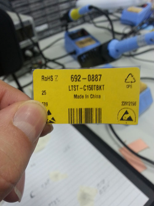
The enlargement lens was not very confortable for me…not enough space to move the solder and view deforming effects. 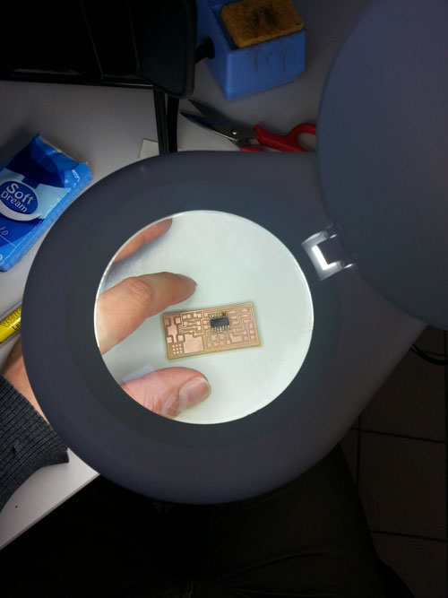
After a shy start, I find my way to solder, just be overheating the board and liquefying the tin in small drops. Then I place the component over two small drops and after a brief re-heating…it was placed. The only problem is that sometimes component result in diagonal position, due to the different size of the mentioned small tin drops.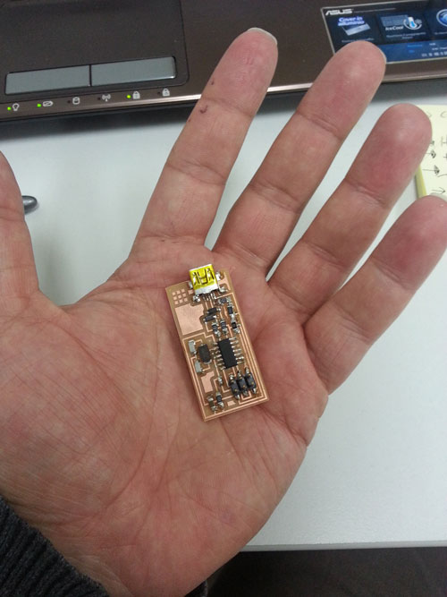
At the end of the day, I try to program the ISP following this tutorial. Programming the FabISP requires basically the following steps: compiling the firmware (make clean and make hex commands), setting the fuse so the board will use the external clock/crystal (make fuse command), programming the board to be an ISP (make program command). The procedure went good (see following figure): "Fuses OK" and "Thank you" means that the ISP has been correctly programmed. 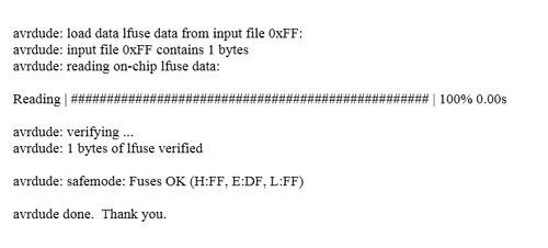
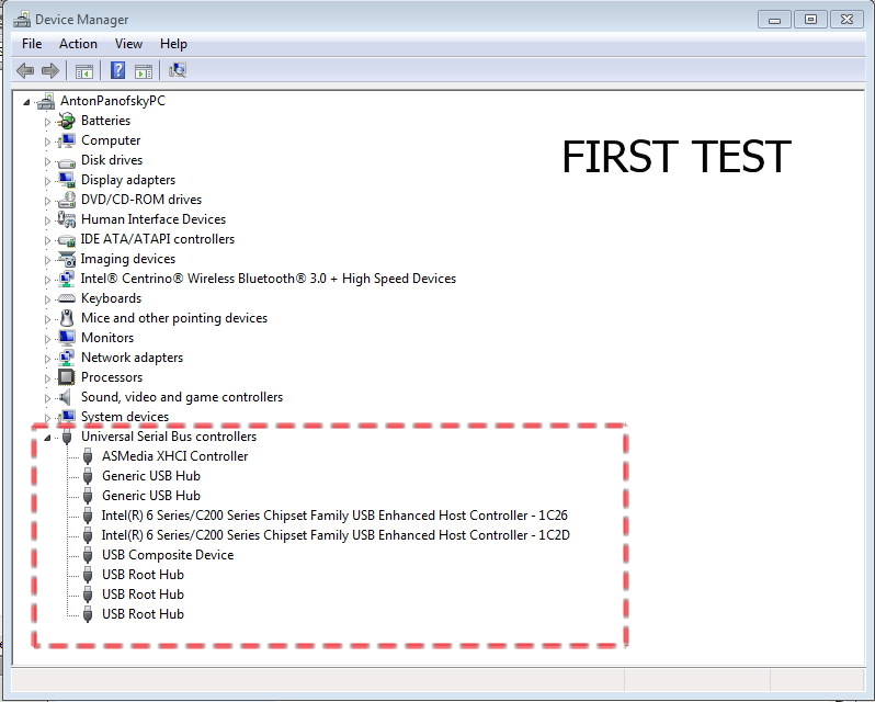
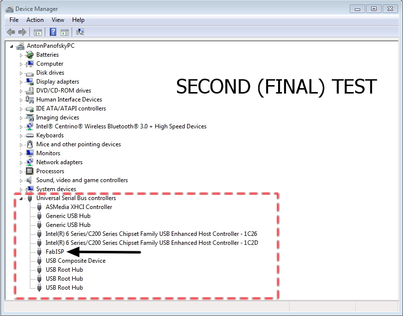
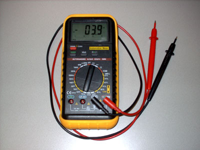 The programming procedure was very long but went good, but unfortunately, at first test, my personal computer (Windows operating system) do no recognize the ISP.At the beginning I do not find a solution for the problem, even checking all the routes, all the soldering and different personal computers. So, following the suggestion of the tutor, I carefully control all the traces, this is the first board I've soldered, so maybe there're problems. How does the tester works ? I need the following help: let me know if traces are working in the right way. So I choose the correct option (sound if trace is correctly connected) and I've started to test all the connection. Connections were correctly soldered, but I've found a very small "bridge" of tin between two traces, maybe the cause of the problem. I've correct this problem using my soldered and then followed again the previous procedure. Everything went right !