Interface and application programming
.
The weekly assignment focuses on write or modify an application that interfaces with an input and/or output device.
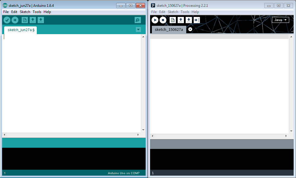
APPLICATION: PROCESSING. The chosen application is "Processing". I've never used it, but my tutors suggest me to start with it because it's very similar, in terms of GUI and code, with the Arduino IDE. I've started to study several tutorials in order to undestand the main functionality. At this link a lot of useful example are available.
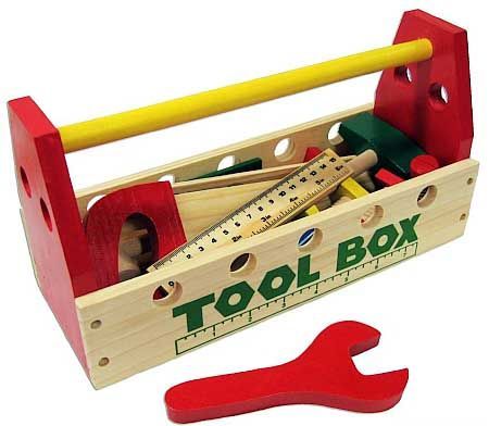
THE BEGINNING. As introduced before, I'm a beginner in programming, so I will try to find some example and deeply understand it. My tool box will be: my FabKit, my output device (a 5gr servo, used to move the fish fins) and a very useful tutorial that I've find at this page.

WHAT IS PROCESSING. Processing is a programming language and development environment and more specifically is an open source programming language and integrated development environment (IDE) built for the electronic arts, new media art, and visual design communities with the purpose of teaching the fundamentals of computer programming IN A VISUAL CONTEXT, and to serve as the foundation for electronic sketchbooks. I've designed a visual application that can interact with an output device (through the FabKit) using a specific LIBRARY of Processing.
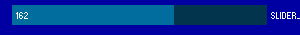
PROCESSING LIBRARY: CONTROLIP5. I've used the Processing controlP5 library to create a simple GUI (graphical user interface). This GUI is basically composed of two sliders that can rotate the servo motor connected to the pectoral fins. The slider is basically a graphical selector of numbers, ranging from a minimum to a maximum. In this specific case the range is 0 degress to 180 degrees (remember that servo does not allow a continuous rotation.
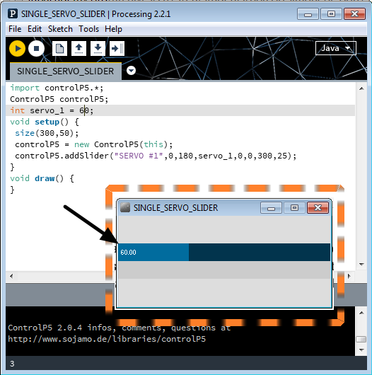
PROGRAMMING THE SLIDER. I've imported the mentioned library and defined the starting value (60) in the defined range of values (0-180). The name of first slider is "SERVO #1". Slider dimension (container) are 300 pixels per 50 pixels, while the slider dimension (data) are 300 pixels per 25 pixels. The two "0" in the string are the reference coordinates of container and data (black arrow indicates the origin). They means there's no shift between container origin and slider origin.
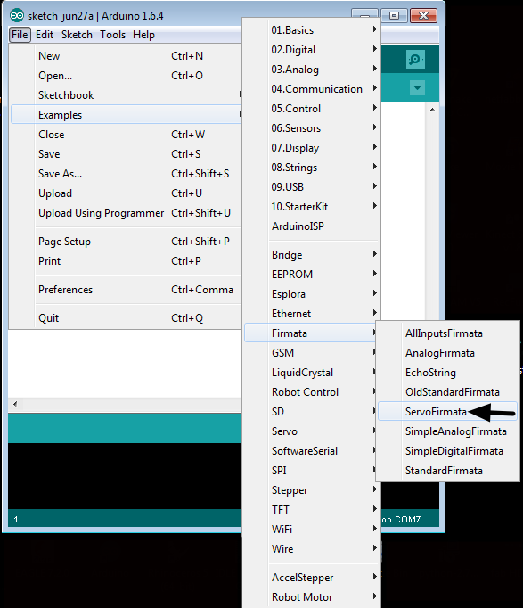
CODE (ARDUINO IDE). I've used FIRMATA for the communication between Processing and the board uploading the sketch. What is FIRMATA? Firmata is a generic protocol for communicating with microcontrollers from software on a host computer. It is intended to work with any host computer software package.
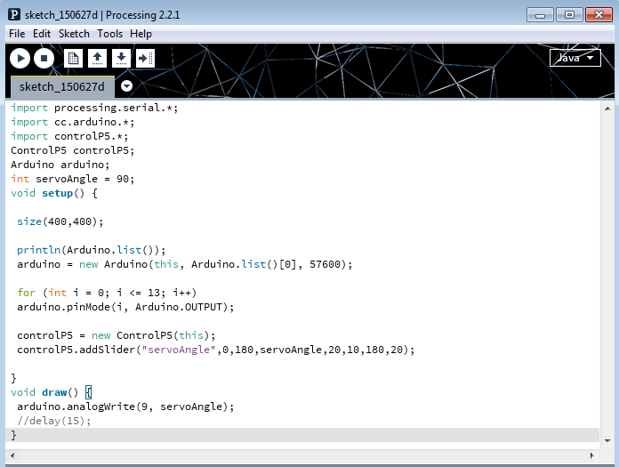
CODE (PROCESSING). I've started from this basic example, trying to undestand the code. At the beginning, very similar to Arduino CODE, there's a list of the mentioned libraries. As you can see, you should import several libraries, but the main important surely is the "import processing.serial" that basically it's a class for sending and receiving data using the serial communication protocol.
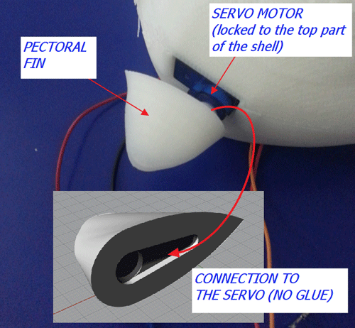
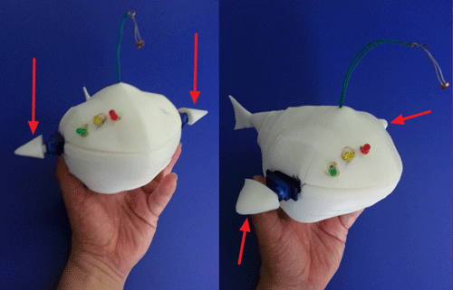
CODE MODIFICATION - Introduction (PROCESSING). I've tried several modification (trial and error method) in order to achieve my result: control two servo, thus control two pectoral fins. The following assignment has been applied to the final project, so I've reported one of the picture just to remind you the position/function of the fins.
CODE MODIFICATION - Part 2 (PROCESSING). What's the meaning of the code ? (1) println(Serial.list()); means to list all the available serial ports. You should note, trying the code, the "COM7" (the used port) appear in the bottom part of the Processing IDE (2) myPort = new Serial(this, Serial.list()[0], 9600); means that you're opening the port you are using at the rate you want (57600 baud in this case) (3) myPort.write(65) means that you're sending a message through out the serial port. IN this specific case we're sending the following instructions: arduino.analogWrite(9, servoAngle);. It means that we're sending through the PWM port numer 9 the rotation in degress of one of the servo.
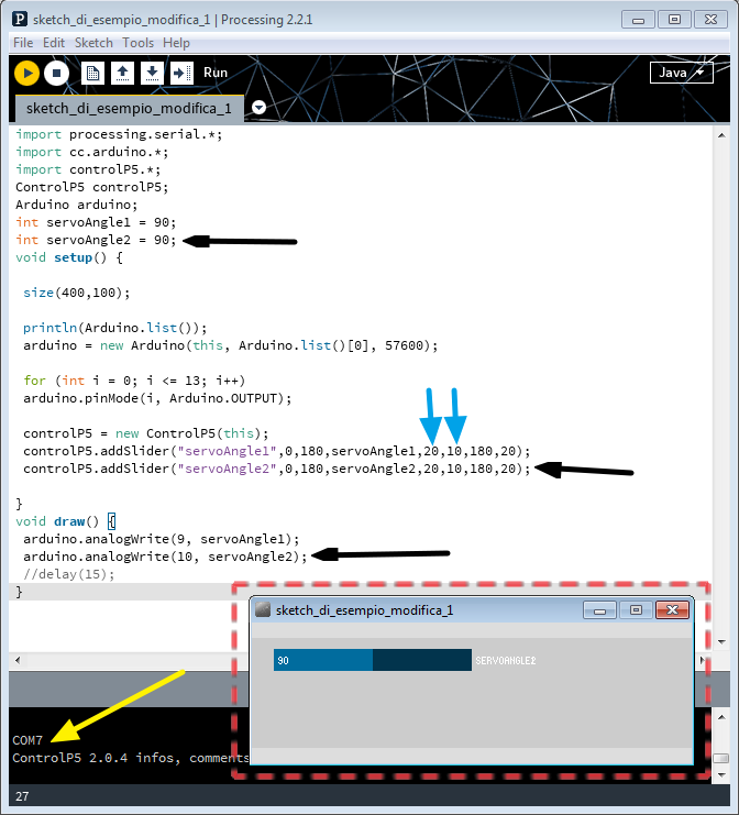
CODE MODIFICATION - Part 3 (PROCESSING). I need now two servos, so I try the following modification, highlighted by the black arrows. I've basically defined a new set of information which "create" a second servo control, setting its dimensions (controlP5.addSlider("servoAngle2",0,180,servoAngle2,20,10,180,20);) and let it communicate through PWM port 10 (arduino.analogWrite(10, servoAngle2);). Please note that the yellow arrow refers to the above mentioned list of available ports. At the beginning I forget about the internal sistem of coordinates and set the same value for x and y coordinates (cyan arrows). After pressing the button PLAY, just one servo appear !!!
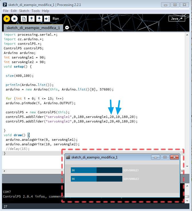
CODE MODIFICATION - Part 4 (PROCESSING). The problem is due to the superposition of the sliders, having both the same coordinates. So, I've shifted of 30 pixels the y-coordinate. Both slider are now visible.
MOVING THE PECTORAL FINS. At the end of the modification, both codes have been sent to the respective recipients: the Firmata code to the Arduino IDE and the modified Processing code to the Processing IDE. The following video shows how the system works. Please note that the plastic body showed in the video is the upper part of the final project. For further details please refer to the Final Project page.
20150628 001608 from antonio burrai on Vimeo.
Download area
The following files are downloadable:
| Type of file |
Description |
Link (Type of file) |
| Code file |
Zipped Arduino Code (Firmata) |
(ZIP) |
| Code file |
Zipped Processing Code (Original example) |
(ZIP) |
| Code file |
Zipped Processing Code (Updated example) |
(ZIP) |