Output devices
.
The weekly assignment focuses on fabrication of an output device and how to control it using the board we've designed in the previous sections.
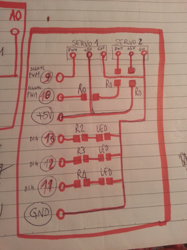
I’ve designed a double output device composed of a visual alarm (a triple led:red, yellow and green) and two servos (that move the lateral fins of the fish). When the depth became excessive, the signal from the input devices (separated into 3 different range of values: 0-500, 500-800 and >800) a led corresponding to the mentioned range lights up. More specifically: 0-500 GREEN LED is HIGH and the others LOW (Arduino code); 500-800 YELLOW LED is HIGH and the others LOW (Arduino code); >800 RED LED is HIGH and the others LOW (Arduino code). RED LIGHT MEANS A VERY DANGEROUS SITUATION FOR THE FISH (excessive pressure – poor sun light). At this point the emergency system move the servos and the rotation of the fins determines the return of the fish to a more comfortable depth. Please note that the fish body is moved by a small DC motor with autonomous functionality (not controlled by the FabKit). Thus, depending on the mentioned light value, servos move.This is the main purpose of the output device.
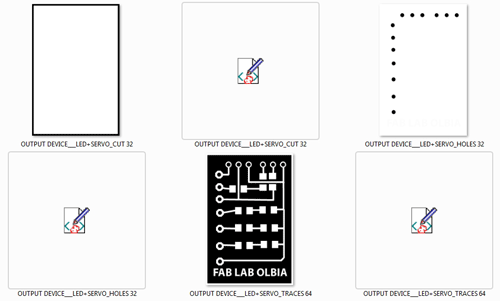
The board have been milled using the attached design files and using the Fab Modules and the Roland SRM-20. The procedure is now well understand. The output device are: LED (i.e.this type) and 5 GR SERVO (i.e. this type).
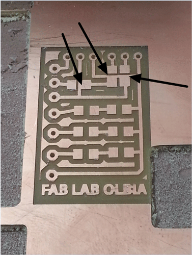
This is the milled board (after the three tasks). Please note the presence of small problem in the zone in which O (zero) ohm resistor are needed. Traces are not correctly divided, so I've correct them using a small cutter.
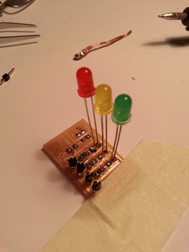
Even in this case I destroy (too much time soldering the components) the SMD LED. This was a great problem, but I consider that I can not use SMD components, because I want the small lights visible as points in the exterior skin of the fish. Thus I’ve used the classical LED.
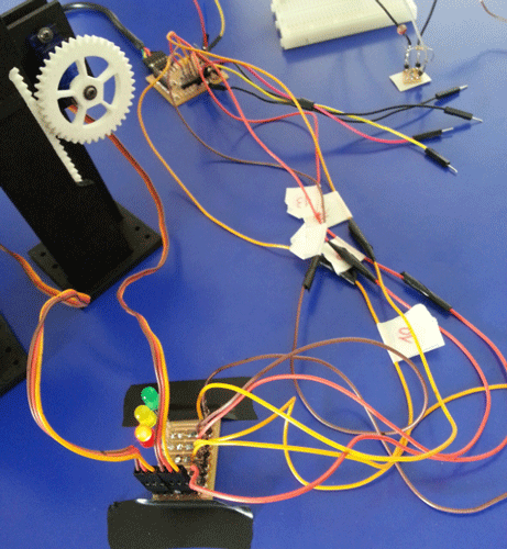
This is the final shot of all the boards I proudly (for first time in my life) designed and milled. The system correctly works. I just need to place all this stuff inside of the fish.
The following video detail how the output details works. The code is also following.Please note that, more specifically: the pin 9-10-11-12-13 (and +5V and GND) have been used to control the output device. As it can be inferred from the following code (not all the code is visible), led pin are 11,12,13 and servo pin are 9 and 10. For a better understanding of the functionality please refer also to the detailed description (and video) available at the Final Project page. 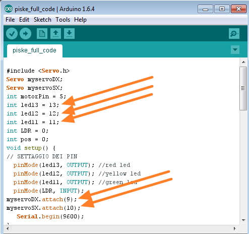
Download area
The following files are downloadable:
| Type of file |
Description |
Link (Type of file) |
Output device - Eagle file |
Board file |
(BRD) |
Output device - Eagle file |
Schematic file |
(SCH) |
Output device (edge cut) |
Image file |
(PNG) |
Output device (drill) |
Image file |
(PNG) |
Output device (traces) |
Image file |
(PNG) |
Working Arduino Code |
Code file |
(INO) |