Input devices
.
The weekly assignment focuses on fabrication of a Fab Kit and an input sensor and, firts of all, understand how a microcontroller board and a sensor wors and how read and interpret the data.
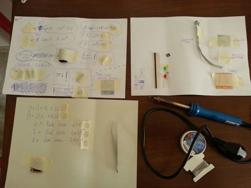
FABKIT FABRICATION. The first part of the weekly assignment is the design of a FabKit (based on this tutorial) and an input device. FabKit, who has been designed for first, has a lot of components, described in the BOM, so I need half an hour to collect them all using the method described by the previous picture.Components: - ATmega 328P-AU
- 1 Resistors 10K
- 2 Resistors 499
- Yellow Led 1206 SMD
- Switch Button
- 2 Capacitors 0.1 UF
- 1 Capacitors 1 UF
- 1 Capacitors 10 UF
- Header 6 Pin
- Resonator 8MHZ
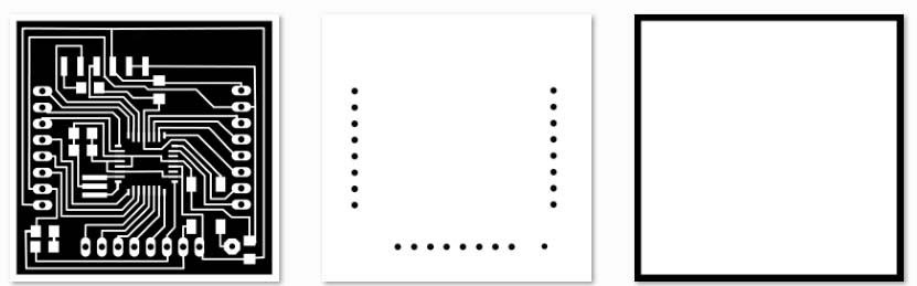
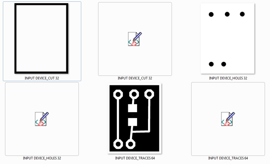
Apart from the components, I drilled the FabKit board using the Roland SRM-20 machine. The PNG files have been downloaded from the assignment page. Three different tasks have been performed: traces (1/64), drill and cut (1/32). As usual, Fab Modules have been used for this task.
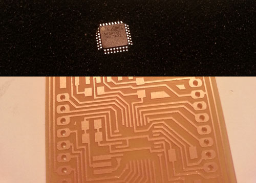
The most complex component is surely the ATMEGA328, that is very small and very difficult to solder. The datasheet could be find at the ATMEL page.
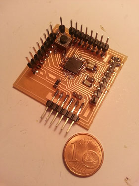
As it can be seen, FabKit is really very very small !!!!
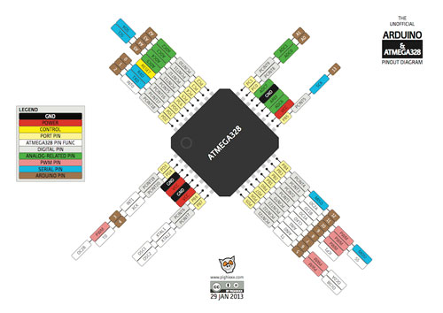
After this, I start studying the ATMEGA328 pinout, it has been quite complex, but at the end, in order to write the BOOTLOADER, I understand I need the following pins: MISO,MOSI, SCK, RESET, VCC and GND. I've trained using Eagle software and tracking all the routes from the processor to the headers, in order to understand how connect the input device to the mentioned processor and components.
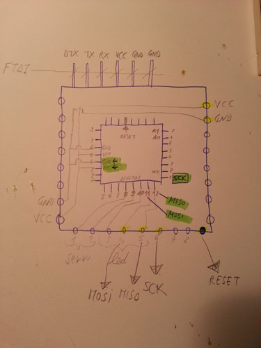
Again a good help for finding the correct usage of the FabKit has been Eagle, who ENLIGHT EVERY TRACE from the beginning to the end. I take note of the pins I’m going to use for the project.
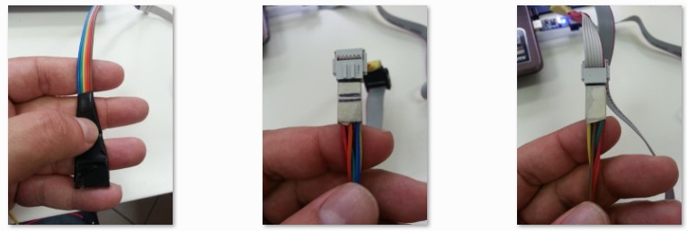
I decide to use an USB programmer, so I powered the FabKit using the FTDI cable. Then I’ve built a cable used to connect the programmer to the FabKit, because there's not a direct existent connection at the Lab.
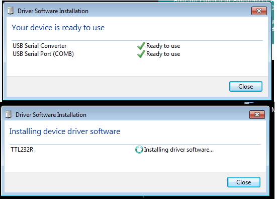
During the above mentioned connection, Windows required lots of drivers in order to make usable even the FTDI cable!!!
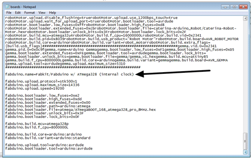
BURNING THE BOOTLOADER. So, once connected the FabKit to the FabKit, using the Arduino IDE, I've changed the boards list in the Arduino folder and the operation went good at first time! Remember to choose on Tools > Board > Arduino Pro or Pro mini (3.3V, 8). I’m very proud of my FabKit.
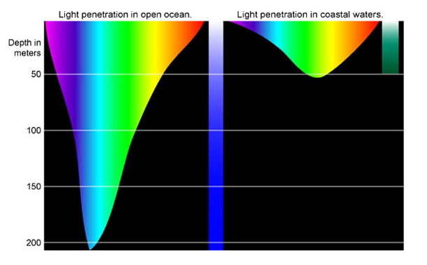
THE INPUT DEVICE. Despite of my final project it’s a fish, I’ve used a light sensor, considering that sun light is RELATED TO THE DEPTH of the water at which the fish is swimming. The deeper you go, the darker it is.

As weel as a submarine, if the depth is excessive and the pressure is too high, several damages can occur to the hull. So the purpose of the input device is to send a constant signal to the processor in order to measure indirectly the depth of water.
The sensor, what it does, what I learned. I've chosen a photoresistor CDS – LDR GL5537-1. Detailed information about the sensor could be find i.e. at this page. The other components:
- Resistors 10K - Header 3 Pin. Some details of the mentioned document have been reported in the following figures.
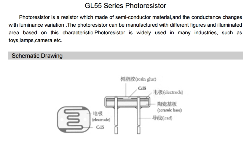
Detail 1/3
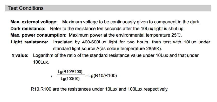
Detail 2/3
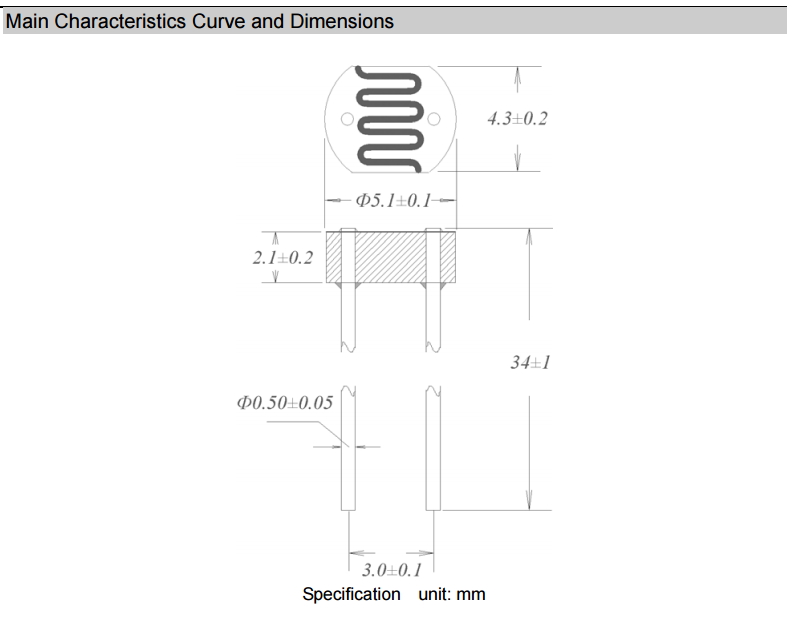
Detail 3/3
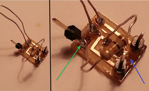
At the end of the soldering I burn the resistor and destroy also a portion of the traces (blue arrow zone) !!! I didn’t have the time to go back to the FabLab, so, just because it was an emergency I place one of the header connector in an unused part of the traces (green arrow) and I’ve also used a classic resistor . It works ! Using the SERIAL MONITOR command of the Arduino IDE, FabKit receives a signal from A0 pin. For a better understanding of the functionality please refer also to the detailed description (and video) available at the Final Project page.
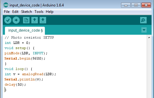 Input device code (preview)
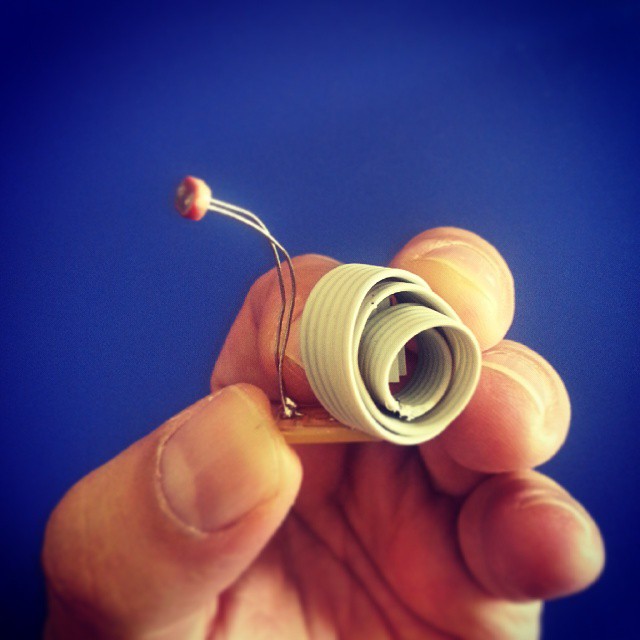
This is an artistic picture of my digital (input) snail !
Download area
The following files are downloadable:
| Type of file |
Description |
Link (Type of file) |
| Input device - Eagle file |
Board file |
(BRD) |
Input device - Eagle file |
Schematic file |
(SCH) |
Input device (edge cut) |
Image file |
(PNG) |
Input device (drill) |
Image file |
(PNG) |
Input device (traces) |
Image file |
(PNG) |
Working Arduino Code |
Code file |
(INO) |