
1. Vimeo Links : One, Two
2. Assignments :
Read a microcontroller data sheet program your board to do something, with as many different programming languages
and programming environments as possible
3. Tryouts
A. From the week4, I produced the Fab ISP. I am supplementing the link here. It shows the steps how to make programming Fab ISP.
For programming and before removing the jumper, I borrowed the Programming Fab ISP from the instructor Eduardo.
http://fabacademy.org/archives/content/tutorials/05_Electronics_Production/Assemble_and_Program_FabISP.html
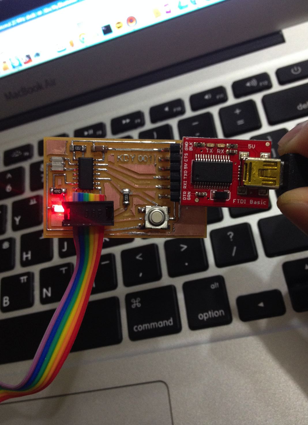
B. Last week I made the KDY 001. So I could connect the Fab ISP to the KDY 001.
I used sparkfun FT232RL which allows me to program boards. So here I connected the Fab ISP with the KDY 001.
Here is the order of connection.
* USB Port > Fab ISP ---- <ISP wiring> ---- KDY001(ATTY) > DT232RL > USB Port *
C. So here is the steps how to prepare the software environment.
1) Download and install the Arduino IDE.
We need to install the Attiny IDE as given here: http://highlowtech.org/?p=1695
So it was either 1.6 or 1.0. I wanted to use the newest version 1.6 but found somehow not working so I uninstalled and tried with 1.0.
Here is the download webpage. http://arduino.cc/en/Main/OldSoftwareReleases
After installing Arduino 1.0 we can follow the steps from the high-low tech.org
2) Installing FTDI. I used the sparkfun FT232RL. You can take a look at the product here.
https://learn.sparkfun.com/tutorials/how-to-install-ftdi-drivers/meet-the-ft232rl
So I had 2 options for installing the FTDI driver. One is given by the instructor.
http://www.ftdichip.com/Drivers/VCP.htm
The other is from the Sparkfun.
https://learn.sparkfun.com/tutorials/how-to-install-ftdi-drivers/mac
I used Sparkfun because my instructor because Eduardo suggested that it would be suitable to the product.
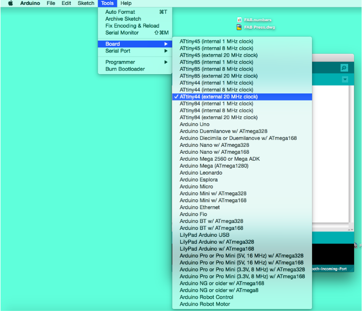
3) After setting up the software I connected the boards. Connecting is important because we need to change the selections of the Arduino IDE.
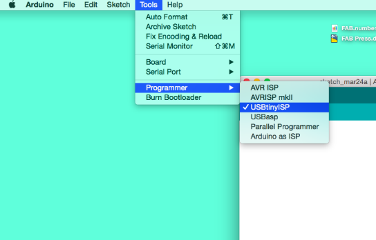
Set board to Attiny44 20Mhz. Set programmer to USB tiny.
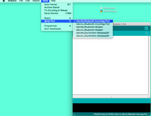
Use the port that is connected. Before plugging into the USB remember the ports. After plugging in the port newly created should be selected.
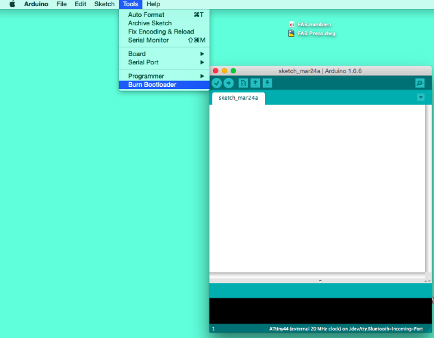
Often it has "serial" and "tty". After Connecting burn bootloader.
4) I used the example coding to make button - LED function.
LED and Button is determined by the datasheet of the Attiny.
For coding I needed to look into 2 things: Datasheet and Board file from Eagle.
Data sheet is found here : http://academy.cba.mit.edu/classes/embedded_programming/doc8183.pdf
Here is the comparison process. I need to see the number of the pin from the datasheet.
I need to read where the LED and Button are connected to the Attiny number.
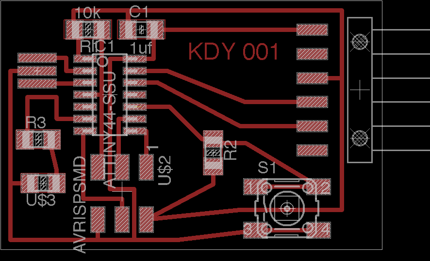
5) We can see that the LED is connected to 6 and the button is connected to 3.
So I changed the number from the example file and it works well.
4. Fabkit
As I finished the KDY 001. Eduardo suggested making the Fabkit for the final project.
So I made the Fabkit.
http://fab.cba.mit.edu/content/projects/fabkit/
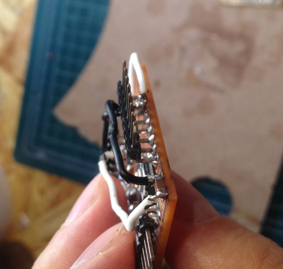
1) It is same as the process of making the fab ISP and KDY 001. However, here comes the frankenstein board!!
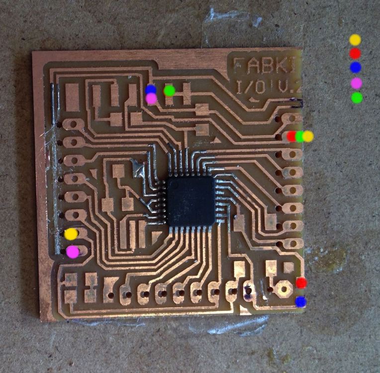
2) As I milled with the Roland SRM-20 the outline was 5mm off the trace.
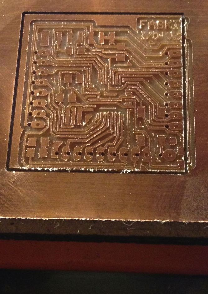
3) However, I wanted to give it a try to save the time.
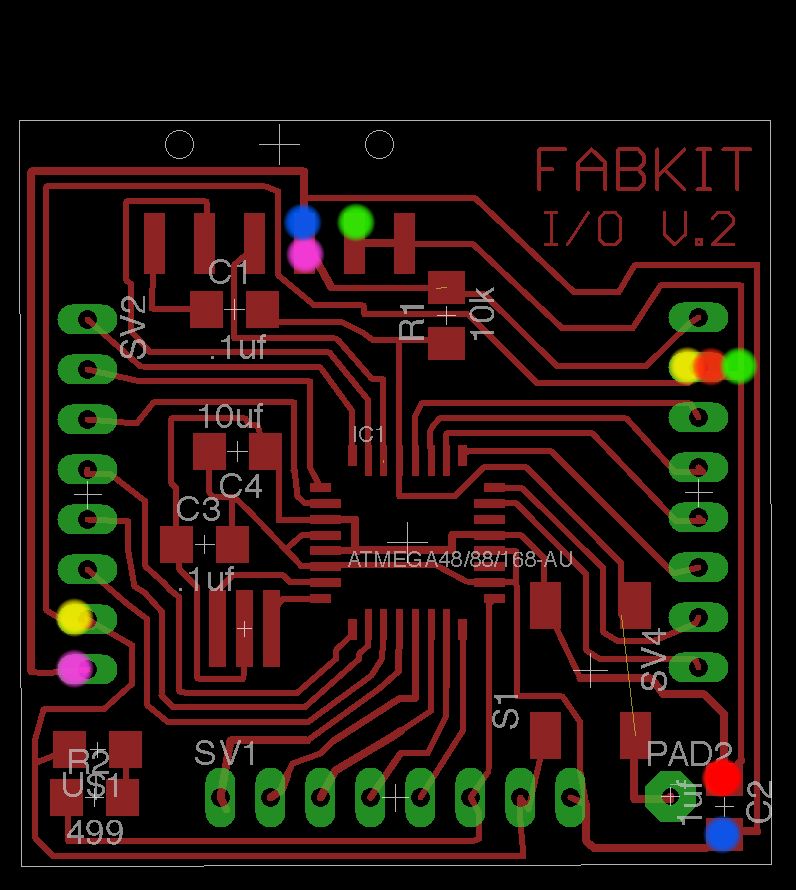
4) Here is the soldering prepartion. I looked into and compared with the fabkit from Eduardo.
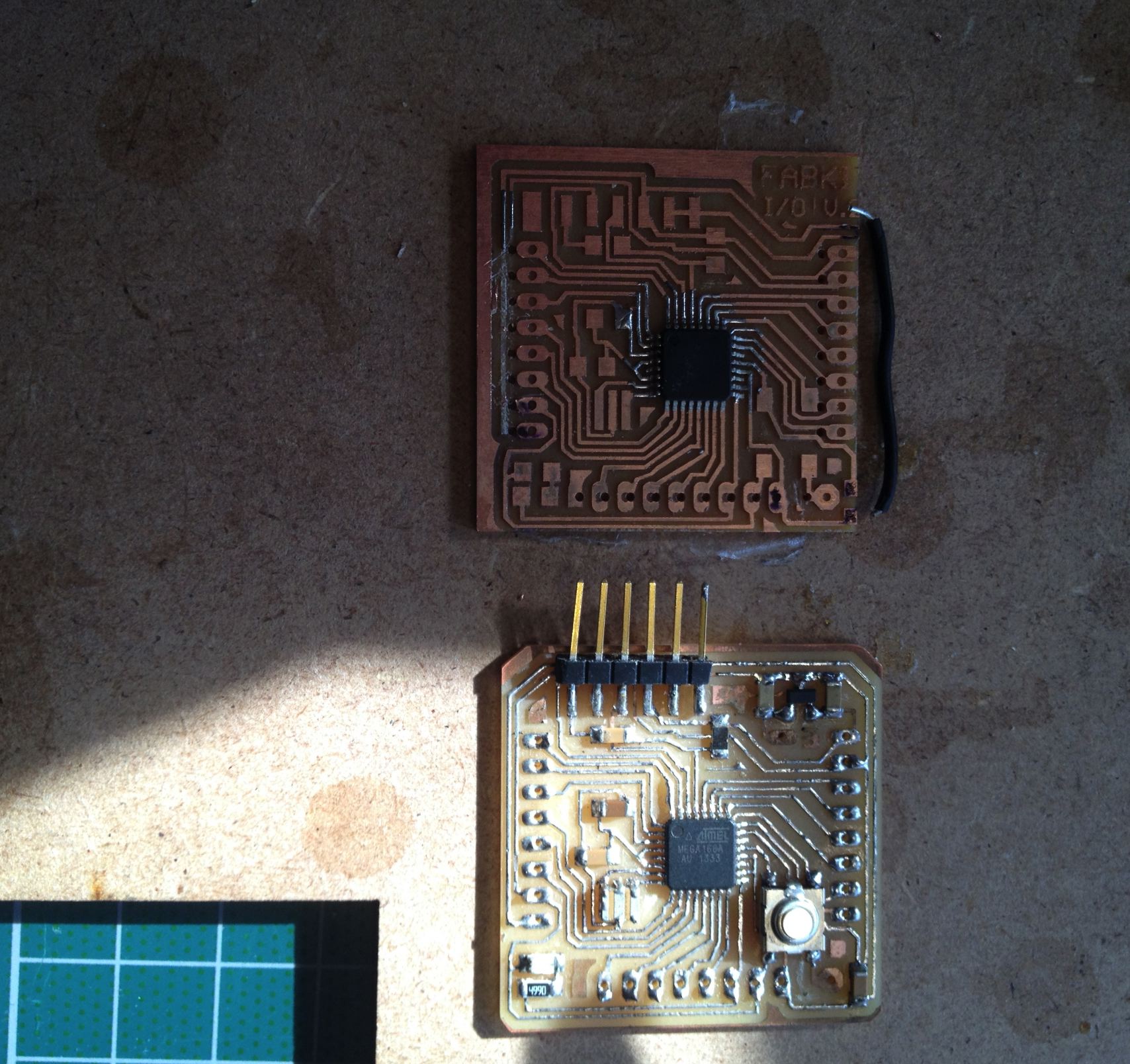
5) I compared the board file with the board to see where to wire. The colors shows where to connect.
You can match the colors to the points where should be wired together.
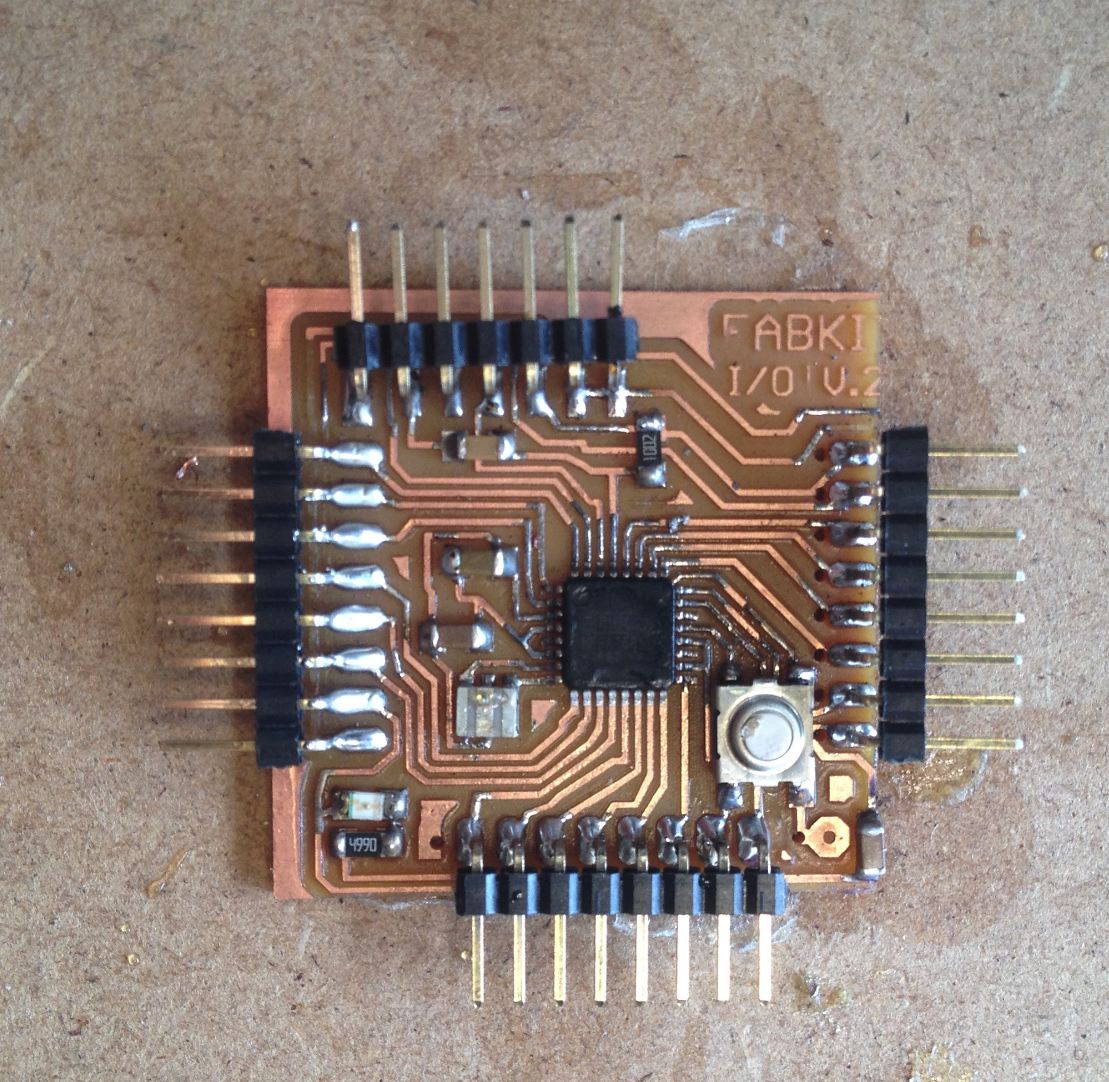
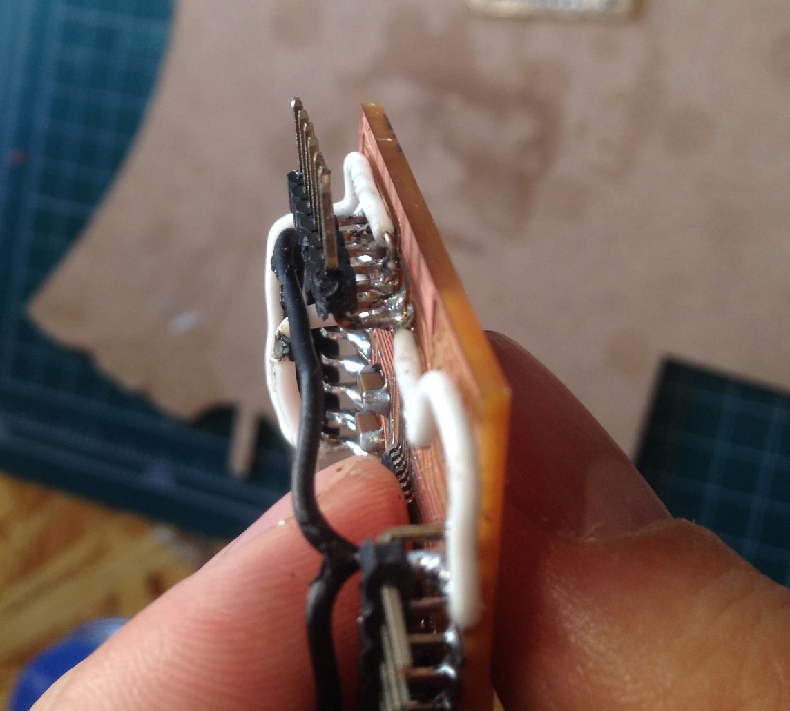
6) I completed the soldering parts. I used male connectors because it is easier to solder.
7) Wiring and wiring and Completed!! You can see that male connector gives a room at the below for the soldering.
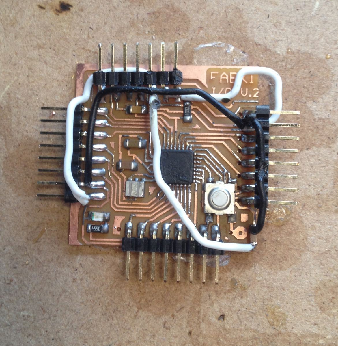
8) Here comes the moment of the test. (Fingers crossed for the luck!) And It works WELL!!!
You can see the lines for the ISP and FTDI. I ducktaped them together.

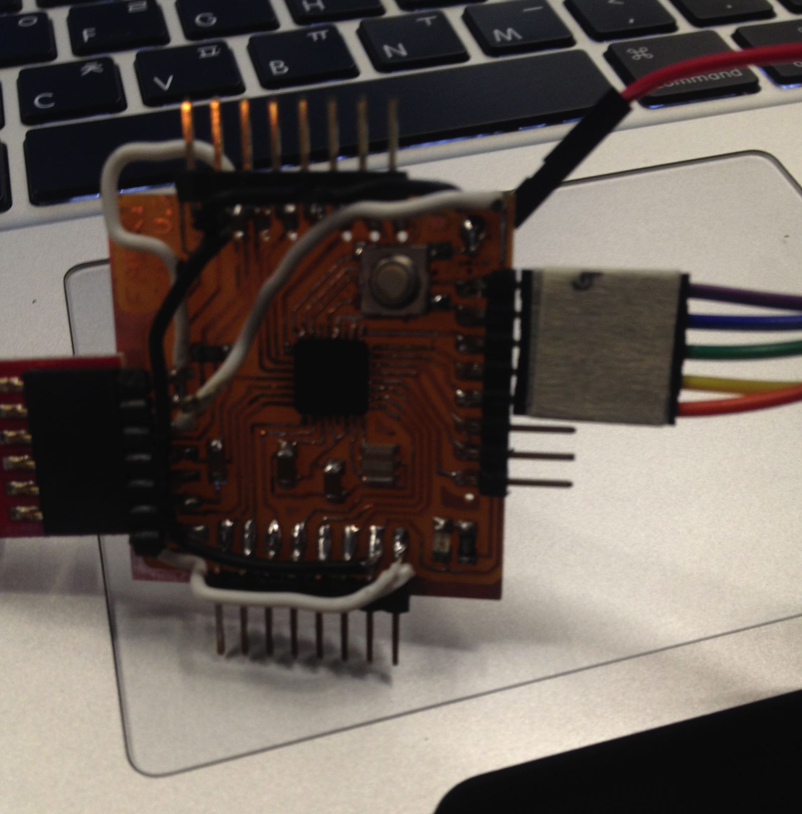
9) As an assignment I played with the coding little bit but the LED is limited to function like time changing.