
<DOWNLOAD FILES>>>
1. Assignment : Document a final project that integrates the range of units covered, answering:
- What does it do? : The robotic hand grabs the magnetic object. One can label the objects with magnetic and grab easily.
- Who's done what beforehand? : I skimmed the Arduino example codes. Analog InOutSerial && Servo Sweep && Servo Knob.
- What did you design? : I designed entire hardware design, coding and calibration.
- What materials and components were used? :
S/W : Arduino IDE, Autocad
Machine: Laser Cutter, Roland CNC Mill
Acryl board : multiple left-overs.
Rubberband : 5
String : 5 of 7 inches
Bolts and nuts : 65 Pair
Wires : 6 lines
FTDI : 1
USB Connector : 1
Servo motor : 1
Magnetic : 3 of various
- Where did they come from? : All from inventory and left over bins
- How much did they cost? : Less that $10.00 USD
- What parts and systems were made? : Acryl pieces for hand
- What processes were used? : Please look below.
- What questions were answered? : Please look below
- How was it evaluated? : Evaluated by the function (grbbing action)
- What are the implications? : By completing the project I found that Plan B is important.
(IN CASE OF SOMETHING HAPPENS && NOT WORKING && MALFUNCTION)
I could improve it if I made another slot for the servo motor.
Also I could make string tension controller from the beginning.
2. WORK
| WORK |
PLANNED TIME |
ACTUAL TIME |
PROGRESS |
|||
| A.PROGRAMMING |
1DAY | 1DAY | 1) I used the Atitiny 44 PCB from the week 11 output servo motor connected to the Hall effect sensor. I used this board and tried to code with Arduino IDE. I continuously tried and managed to work but it was by fortune because Attiny 44 was not compatible with digital servo signal. |
|||
| |
||||||
|
1DAY
|
2). PCB
&& PROGRAMMING : As I switched to the FABKIT Atitiny168 from
week 7, I made the new sensor PCB board for the hall effect sensor. The programming changed by adding "if, else." Because Atitiny 44 was not able to react to the both N,S of the magnetic I needed to figure out by "Either OR(||)" code. However, I was not sure what number is reading from the analog hall effect sensor. I added code from the Arduino Examples on sensor read to see the number. The serial port reading was able to give the number of 508~520. Later I calibrate the numbers to move on both N and S of the magnetic. I also added Counter to see if the sensor is reading from both N and S.  Here is the final test |
|||||
| B. Hardware |
1DAY
|
1DAY
|
1). I decided to use the laser cutter because it shrinkens the time of manufacturing. However, it was also time consuming process. I started with making holed for the bolt and nuts and The holes were small that I re-designed to bigger holes. Also I wanted the joints of the fingers fit perfectly to prevent the fingers to fold back. I needed time to find the perfect size because of the KERF. 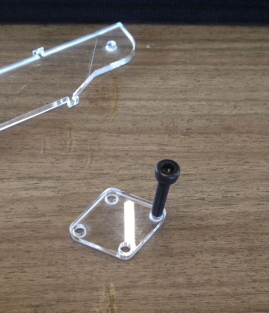 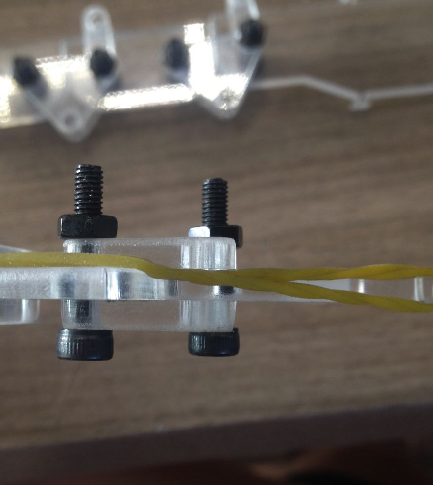 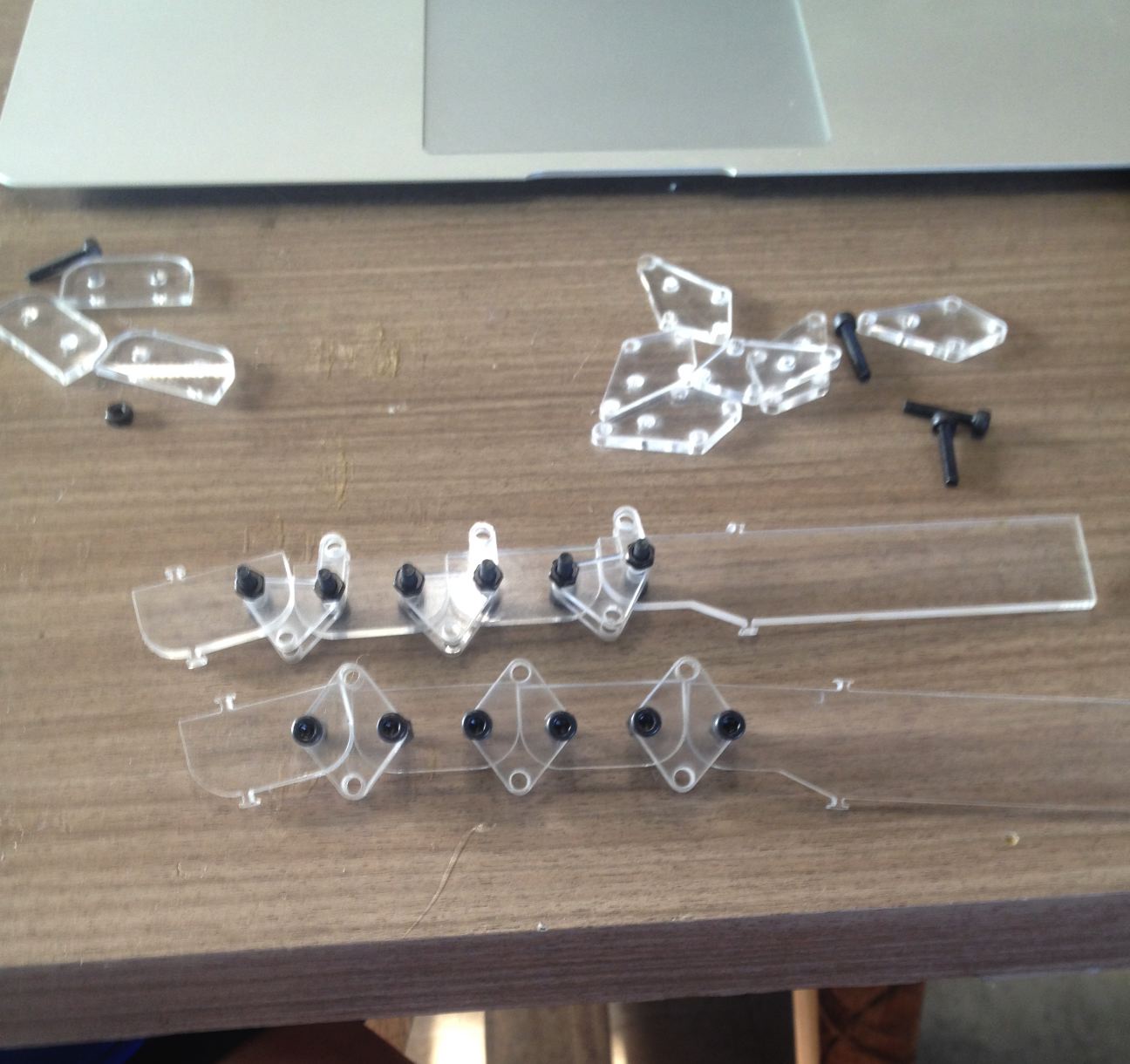 2). However, from the beginning I found that the joints of the fingers needed teeth to work smoothly and I decided to move on to the major change. Instead of making teeth I made bolt to stop finger to move backwards. 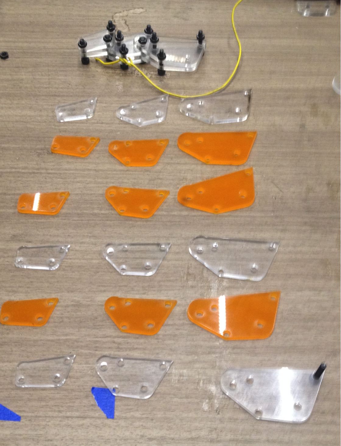 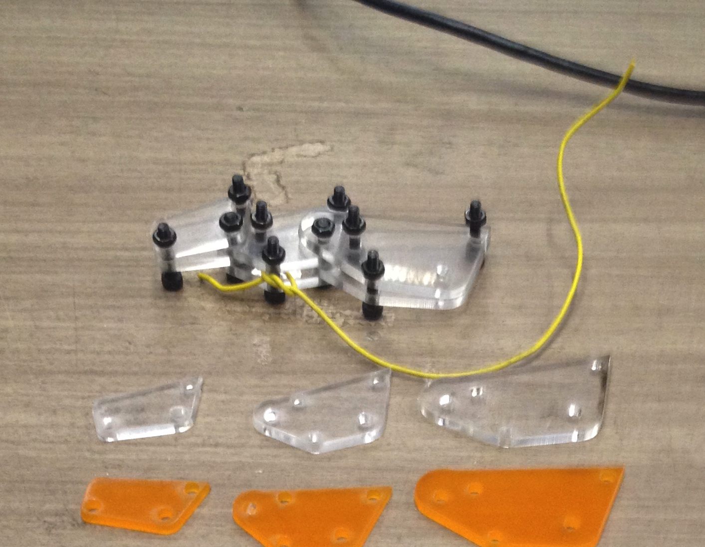 3). I assembled one finger and tested its function. The rubber band that I used stuck in-between pieces braking movement, so I managed it. |
|||
|
1DAY
|
4). Finally, I modified the design and it was also long time consuming. I needed to find size of the holes for horizontal thumb fixture. I made multiple samples to satisfy KERF. After designing I found the thickness of the servo motor is exactly seven sheets of acryls. 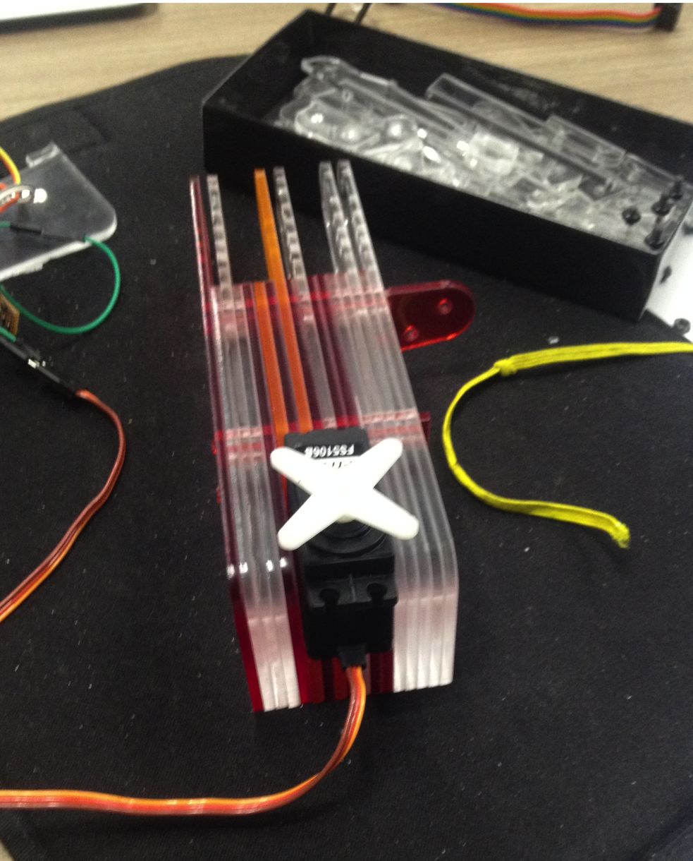 5). After assembly I found direct connection of the 5 strings to the servo is not favorable. The strings were loosen off after few moves. So I needed fixture mechanism that combines all of the strings and servo motor together. I made this yellow sliding board able to calibrate tension of the strings. I used only one servo motor that the tension was strong that broke the wire so I strengthened it. As a result, it works nice!! 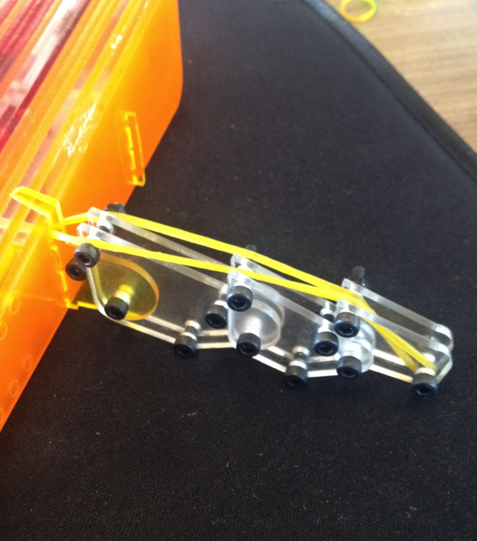 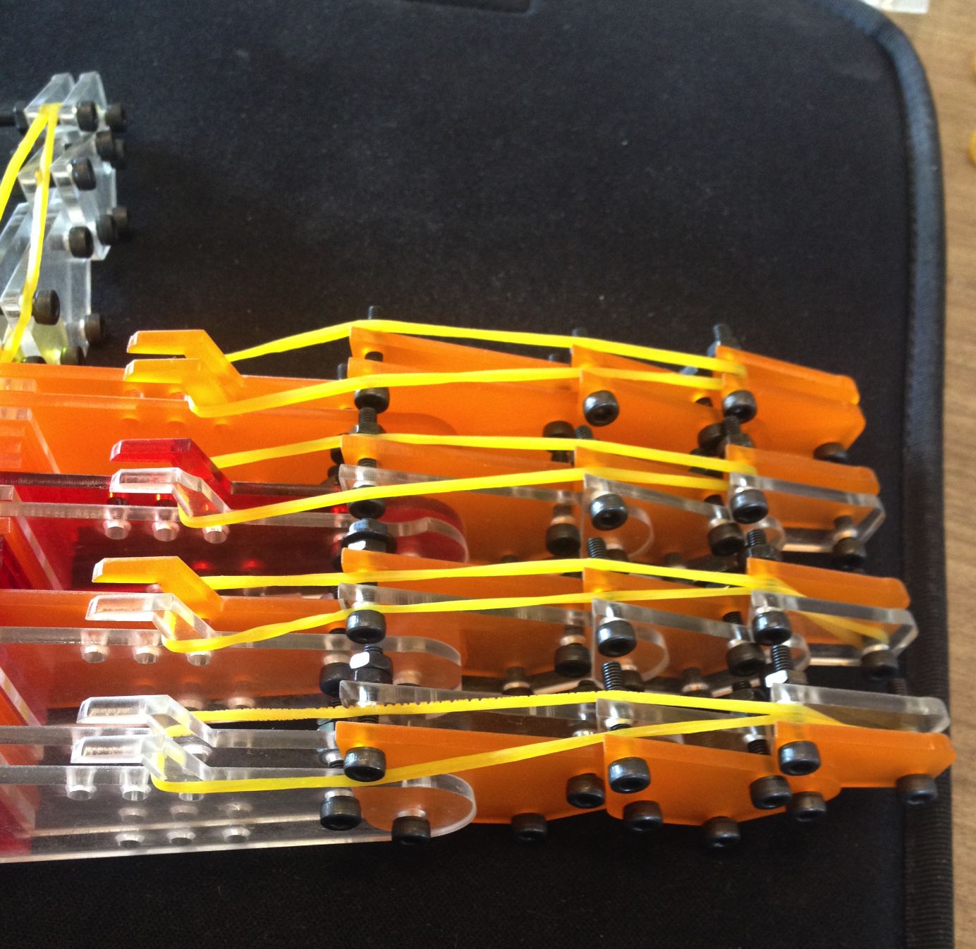 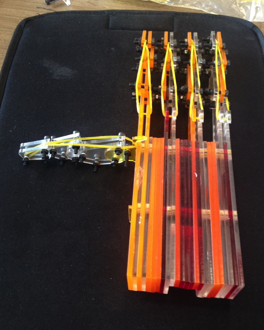 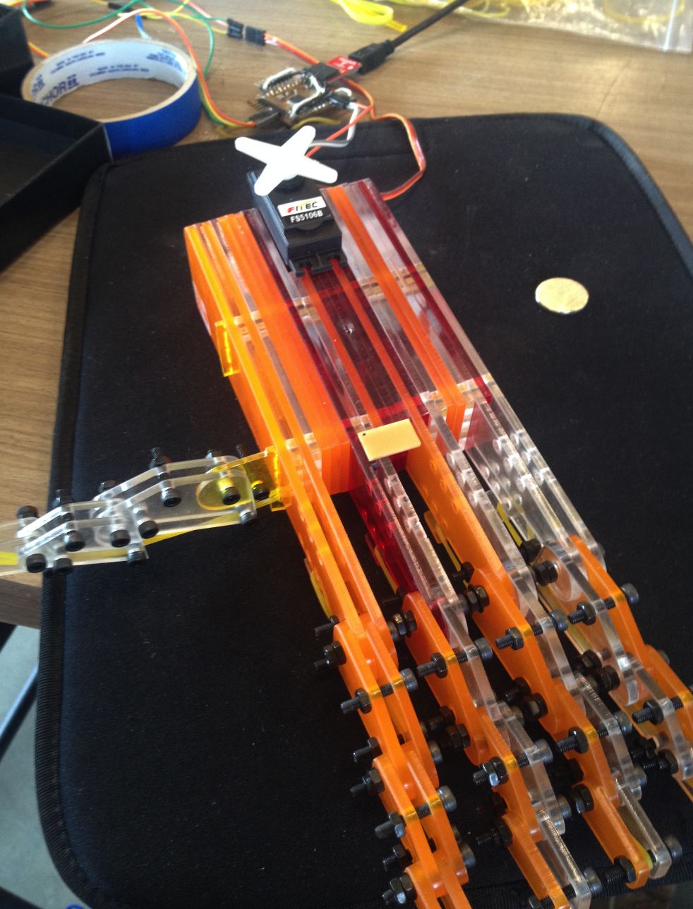 |
|||||
| TOTAL |
2 DAYS | 4 DAYS | ||||