week 13 mechanical design, machine design
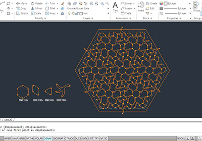
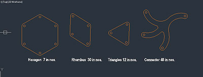
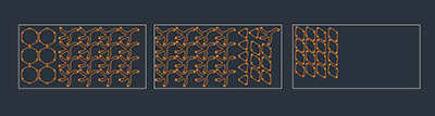
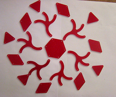
As our final project involves motion, we wanted to develop basic module rotating for this assignment. We made a overall drawing for eventual design and extracted basic module out of it. Each individual component is cut in 2.5mm cast acrylic. Various materials like carboard, PVC sheet prior which is shown in the final project page (week 17). These components are joined useing machine screws 3.5mm dia and 5.5mm high. Tolerance of 0.5mm was considered between screw (3.5mm dia.) and holes made in the component (4mm dia.). These are lessons learnt hard way (Refer process for final project).
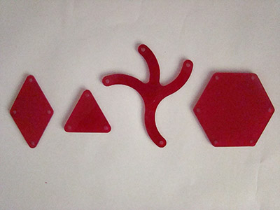
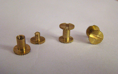
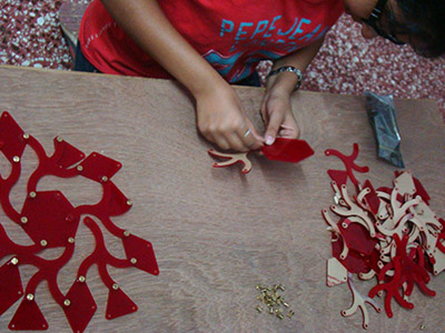
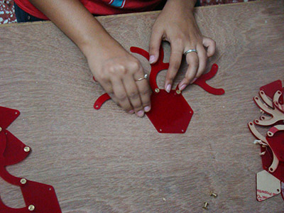
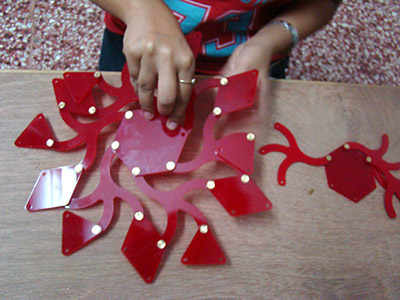
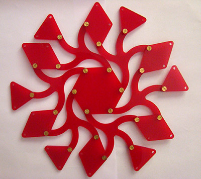
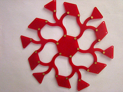
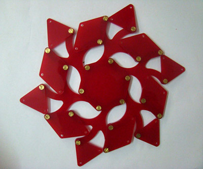
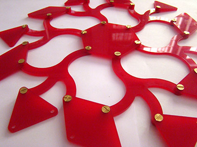
We were very happy to make this using machine screw connection over revets for two reasons. First, the movement was quite smooth. This is because the height of screw is fixed and the pipe joining two component is consistant. This is much more precise over revet fixed manually where the pipe is broken uneven. Secondly we saved a lot of time and efforts from reveting each piece. However this is still not the full proof method. We are not completely satisfied with the results. Tolerance between two thicknesses of components and height od screw is only 0.5mm. This is not enough. If we lock the screws tight, movement is not as smooth. If we keep screws little loose, they keep opening after 5-6 movements. We have a long way to go until finding a right solution. Please give us feedback on this.. All sugessions, ideas, comments are most welcome...