week 11 out put devices
I milled the boards while Ashris soldered and programmed them
This week’s assignment was a follow up of the last week and was similar to it. For this assignment we had to make a pcb which had any one of the output devices from the list of devices mentioned in the list. We decided to go with the RGB LED board which changes colour from red to green to blue.
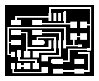
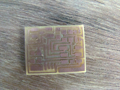
After completing the board layout we converted the PNG to .rml file for the ROLAND MODELLA machine to mill the pcb. After milling we followed the same steps as done in "input devices" like, collected all the required components systematically. Labelled on a sheet of paper. Sequence of soldering and direction of components in specific case. Then soldering was the next step which hardly took more than 30 minutes.
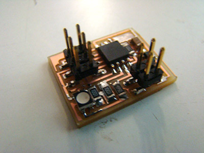
Now for the programming part, we used the AVR ISP and the code from the RGB LED section of the assignement.
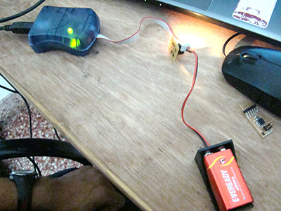
Everything worked perfectly and the message showed was exactly according to the ASO Tutorial
So it works!