What is my Final Project?
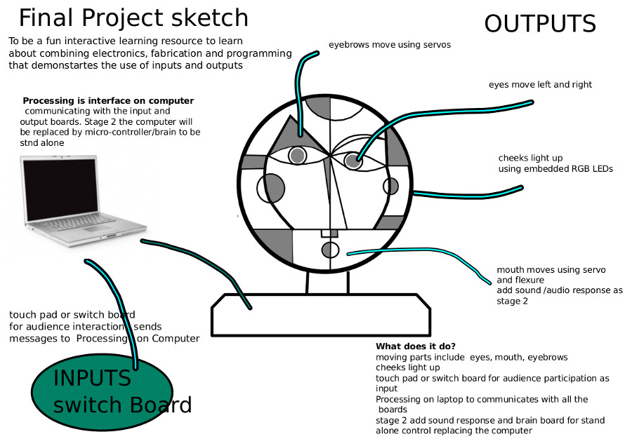
Kleebo is an engineered arts project for learning about electronics, programming and fabrication. I have taken inspiration from a portrait by Paul Klee to create an interactive face with moving parts that demonstrates inputs and outputs.
What will it do?
The
audience can interact with Kleebo via a switch board. The 4
switches provide 15 different combinations of actions moving the
eyes, eyebrows and mouth and lighting up LEDs . I intend to add sound
and a more interesting touchpad at stage 2. The Kleebo face sits
on a desk top supported by a press-fit structure.
Who's done what beforehand?
I
have researched a variety of robotic projects, portraits and
puppetry to understand facial expression and provide engaging
interaction.
What materials and components will be
required?
Where will they come from?
What do I need to order?
How much will it cost?
|
Number of parts to make |
Part or system of final Project |
Material / components required/
what needs to be ordered |
Cost |
|
1 |
Face and press-fit support structure Eyebrows and mouth |
3mm ply 600x300mm x2 |
|
|
2 |
cheeks |
Embedded LED’s in epoxy resin 2 RGB LED’s epoxy resin preparation of mold using 2 blocks of wax
50x50x50mm using all supplies from Fab Inventory |
|
|
3 |
1 RGB LED board |
Using all supplies from FAB inventory |
|
|
4 |
5x 180degree servos |
To order
£2.90 each from 4tronix tower pro sg90 Micro servo |
|
|
5 |
Switch board |
All parts from Fablab inventory |
|
|
6 |
Brain board to replace computer at later
date |
All parts from FAB inventory |
|
|
|
|
|
Total Cost
|
What parts and systems will be made?
Fabrication
|
Parts to be made |
Process used and decisions to be
made |
|
Face |
Lasercut with final changes to design
adding flexure to move mouth, cutout areas for cheeks
to be embedded Pivot points for servos, cut grove for
arch of servo for eyebrow |
|
Pressfit structure to hold face so able
to sit on the table |
Lasercut and decide on final design and
size, position of servos and pressfit connectors |
|
Pressfit connectors to hold servos |
Lasercut – finalise size and position on
face Test press fit connectors to check it
will hold servos |
|
eyes |
3d print in white with pupil –
improvements to existing shape – check size |
|
eyebrows |
Lasercut, decide on movement, pivot
point, and how to connect them to the face, how to
connect eyebrows to servos and arc of movement |
|
cheeks |
Draw up in Rhino – cutout mold on shopbot
– use epoxy resin to embed LED on mini board to allow
for connecting |
|
mouth with flexure |
Laser cut mouth and think how to attach Flexure and servo to move mouth, where to
place servo? Consider pivot point |
Mechanical Design
Moving
parts of the face using servos, flexures and linkages to
transfer rotary motion to linear motion.
Mechanical issues that need to be resolved
are;
Electronics
The Network
A complex system with simple individual nodes. I have chosen this system to be scalable allowing the addition of other nodes creating a modular system easier to debug allowing each part to be made independently. Hopefully this will make the network easier to manufacture, change and mend.
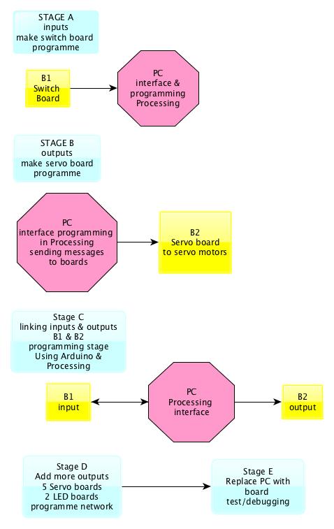
Boards
I am designing and making
|
Boards |
function |
|
B1 |
Switches board with 4 buttons to be
interface
|
|
B2 x 5 |
Servo board x 5 to move parts of face – eyes,
mouth, eyebrows |
|
B3x 2 |
RGB LED board to light up cheeks |
|
B4 x 2 |
Mini board for embedded LEDs
|
|
B5 |
Brain ATtiny 44 to replace computer and
make project stand alone |
|
B6
|
FTDI connector with 2x3 header as bridge |
Programming
I will use Arduino to programme my boards and processing to communicate on my computer. Switch functions below showing
15
options from 4 switches
|
Switch functions
providing 15 different combination of actions |
|||||||
|
Switch1 1000 |
Switch2 0100 |
Switch3 0010 |
Switch4 0001 |
Number function |
actions |
Combined actions |
combined sound MP3 files on MP3
shield for Arduino |
|
0 |
0 |
0 |
0 |
1 |
Nothing |
|
|
|
0 |
0 |
0 |
1 |
2 |
eyes_move left/right |
|
|
|
0 |
0 |
1 |
0 |
3 |
eye_brows Up/down |
|
|
|
0 |
0 |
1 |
1 |
4 |
|
Eyebrows eyes
|
|
|
0 |
1 |
0 |
0 |
5
|
mouth
moves down/up |
|
|
|
0 |
1 |
0 |
1 |
6 |
|
mouth eyes
|
|
|
0 |
1 |
1 |
0 |
7 |
|
Mouth eyebrows |
|
|
0 |
1 |
1 |
1 |
8 |
|
Mouth
eyebrows
eyes |
|
|
1 |
0 |
0 |
0 |
9 |
Cheeks
light up |
|
Sound |
|
1 |
0 |
0 |
1 |
10 |
|
Cheeks
eyes |
sound |
|
1 |
0 |
1 |
0 |
11 |
|
cheeks
eyebrows |
sound |
|
1 |
0 |
1 |
1 |
12 |
|
Cheeks eyes eyebrows |
sound |
|
1 |
1 |
0 |
0 |
13 |
|
Cheeks
mouth |
sound |
|
1 |
1 |
0 |
1 |
14 |
|
Cheeks eyes mouth |
sound |
|
1 |
1 |
1 |
1 |
15 |
|
Cheeks Mouth Eyes eyebrows |
sound |
What processes will be used?
|
Processes involved in Final Project |
Where the process is used in the
Final Project
|
|
CAD |
Rhino for 3D and Inkscape for 2D |
|
Machine Cutting |
Lasercutter for main structure and
Shopbot for 3D mold of cheeks |
|
Electronic Design |
Using Eagle to design all boards |
|
Programming |
Arduino |
|
Molding and casting |
Cheeks will be molded with embedded LED’s |
|
Inputs |
Switches |
|
Outputs |
Servos and LED’s |
|
Networks |
Building
a network |
|
Mechanical Design |
movement
of parts of face using linkages via servos changing
rotary motion to linear and using flexures to move
mouth |
|
3D printing |
eyes |
|
Applications |
Processing |
What tasks need to
be completed and in what order?
1.
Position of moving
parts, and servos to be added to final CAD files
2. Work out pivot point
of eyebrow, servo position and grove in face
3. Final CAD files for
the structure, size, moving parts and pressfit positions
4. Lasercut final face,
parts and structure and test stability
5. CAD drawings for
mold of cheeks, make using Shopbot, prepare mold ready for epoxy
resin and embedding LED’s on mini board
6. Connect all parts to
face
7. Design and make all
boards
8. Programme boards
9. Test, debug,
improvements
10. Final making testing
and debugging
What questions need to be resolved?
How
to attach servos?
How
to work out the pivot points of the eyebrows?
How
to attach the eyebrows?
The schedule
|
DAY |
Program |
Electronics and network |
Mechanical Design/problem solving |
Fabrication |
Assembly |
Debugging and testing |
|
1 |
Write programs for Servos |
Make servo
boards |
Resolve and test eyebrow attachment and
servos in cardboard |
Finalise Design CAD Lasercut tests for structure |
|
|
|
2 |
Write programs for LEDs |
Make LED boards |
Resolve eyebrow and servos attachment In ply |
Lasercut face and pressfit structure Shopbot cheeks to make mold Start mold process |
Assemble pressfit structure |
|
|
3 |
Debug programs |
Make mini LED boards and FTDI connector and
header board |
Work on lasercut tests of structure and
fittings of servos Fittings for eyes And mouth |
1-3d print eye 2-make mold with embedded LED boards embedded 3-test pressfit structure, make other parts does everything 4-fit together? |
|
|
|
4 |
|
|
Lasercut structure tests Fittings of servos |
Finalise face, parts, structure of pressfit
and assemble |
|
|
|
5 |
Finalise programs |
Assemble and test network |
|
Finalise cheeks and start fitting parts
together |
Fit parts of face and structure |
|
|
6 |
|
Assemble and test network |
|
|
Assemble all parts and test |
Debug and test |
|
7 |
|
|
|
|
Assemble
all parts and test |
Debug
and test |
|
8 |
|
|
|
|
|
Presentation |
How will it be evaluated?
To
evaluate the final project I will take it in to school and get
feedback from a group of children and fellow teachers.
Criteria for evaluation
If
the children enjoy playing with Kleebo and want to get involved
in reprogramming and making changes to the original design.
Further developments