- Introduction:
The window shutter system folds and unfolds depending on light conditions. Two pairs of operable shutters are connected to each other via hinges, and to the frame via socket joints and wheels, which slide on a rail, which is embedded within the frame.
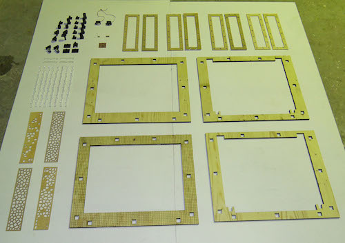
The Shutter system is made of 3 main components;
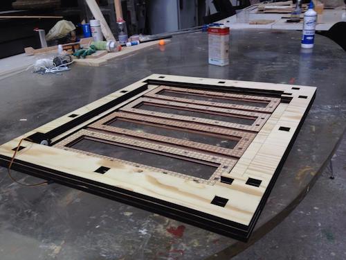
1) Main frame:
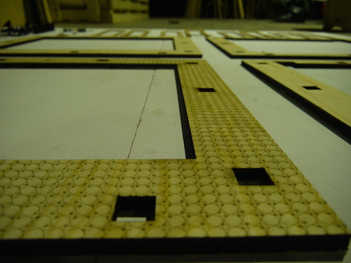
Made of four layers of 12 mm thick plywood, this frame forms the base of the system. The stacked layers of different shapes form grooves, which will then function as the rail that the shutters will slide on and hence facilitate actuation, and slots that provide space to fit in the joints. And ultimately, it holds the shutters in place.
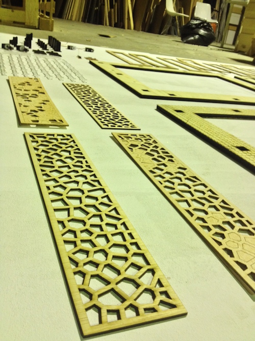
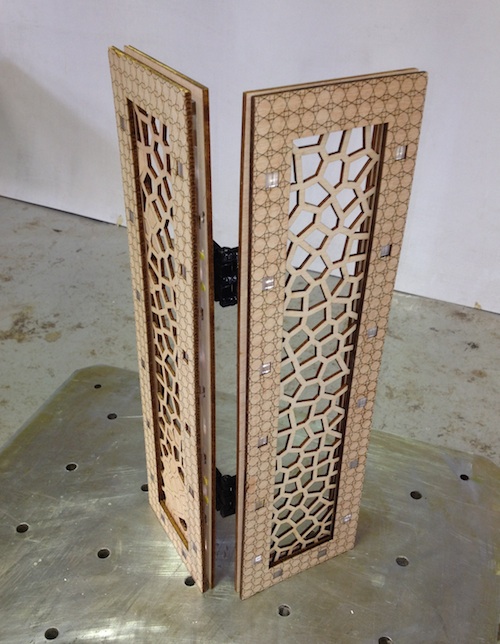
2) Shutters:
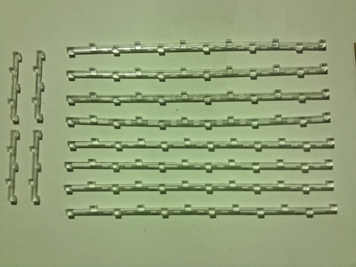
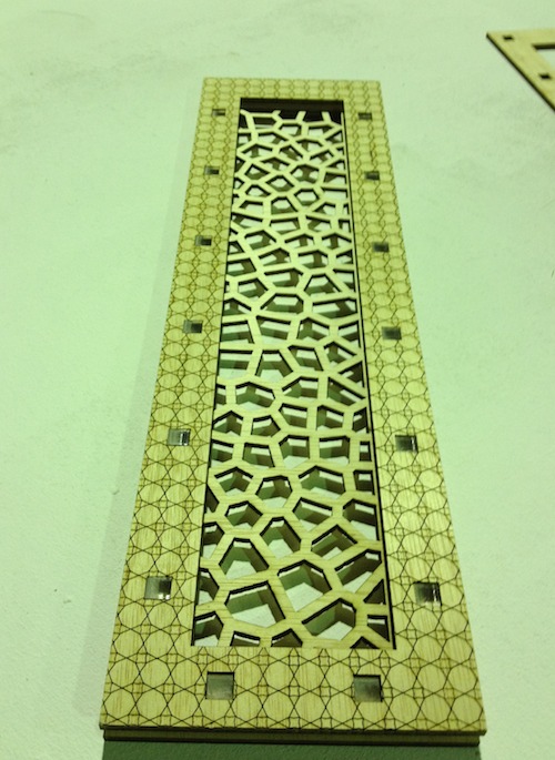
Each shutter is made of two layers of 15mm thick frames, separated by three 15 mm thick acrylic combs, from the sides and the bottom leaving a slot (fourth side of the frame). Different designs can be placed through the slot.
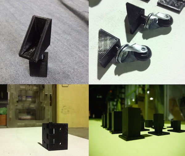
3) Hinges and joints:
The hinges hold each pair together allowing limting the movement of the shutters. The joints connect the shutters to the main frame from the bottom right and left corners, to the motors from the upper right and left corners. The inner frames are connected to wheels from the bottom and to cylinders from the top to keep in from toppling to the front.
- The Process:
Conceptual design (Rhino):
Since I have no experience whatsoever in making window shutters, I started by drawing a basic 3D model which will help me better visualize my idea and eventually help me simulate the actuation mechanism where applicable.
Mechanical Design:
Percision is key here; a fraction of a mm makes a difference!
The mechanical design was a big challenge to overcome. Searching for/ eliminating all the unforeseen errors virtually is nearly impossible. For that, I decided to make a simple basic prototype of one side of the shutters to test if what I had in mind can be achieved. The more I worked on the design, the more I faced confusing situations. The time I allocated for design is nearly over and I feel that its time to fabricate the frames to a tangible prototype which will be tuned later to fit the job.
Check Mechanical Design page
Materials and Deliveries:
I brought the 5mm /4mm boards and swivel casters from Servei Estacio.
The servomotors haven’t arrived yet from Hobbyking.
Fabrication:
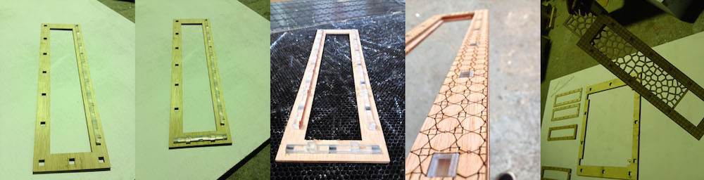
The Shutters (Multicam Laser-Cutter):
- Cutting:
I refered to Fab lab BCN Wiki for technical specifications.
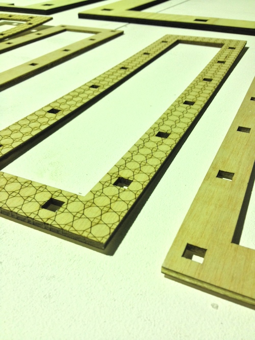
The challenge I faced here is to cut the squares, which the acrylic comb will fit in. the squares are either too small or too big for the acrylic. After several attempts of modifying my design then fabricating, I finally reached the perfect fit: 0.3mm offset.
- Engraving:
After engraving the first frame, I noticed that it started bending and I realized that the speed and power values I entered are not suitable for the material and the detailed pattern I was using which resulted in bending/ kerfing the wood. I then adjusted the speed/ power to 90/ 60 which gave cleaner results.
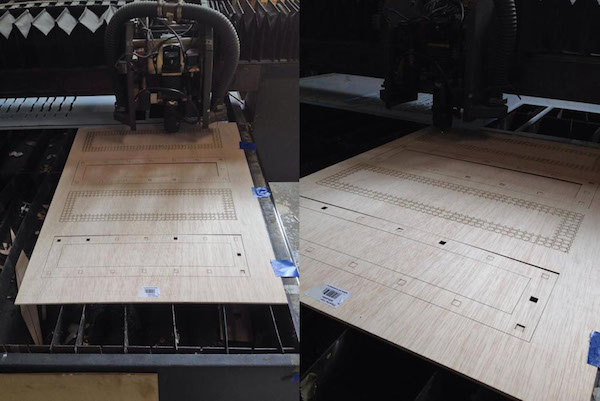
The Main Frame:
- Cutting:
Cutting the boards took more than I expected, as I had to set the speed to 4 and the power to 390.
- Engraving:
The problem I faced here is the pierce power, which was set to 150. This resulted in small holes on the pattern. Always remember to set the pierce power to 0 when engraving to avoid this problem.
Warning: Never set the machine to maximum power, doing this might ruin the machine.
Joints and Hinges:
- 3D Printing (Makerbot):
I first printed the joints for one side of the shutters to test the mechanism and the fitting tolerances. Printing 36 parts took a tremendous time to complete.
Assembly:
The Shutters:
The Main Frame:
Joints and Hinges
Programming
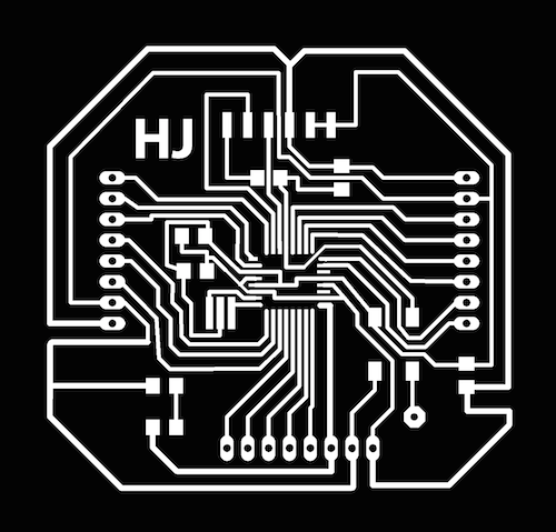
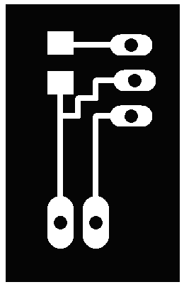
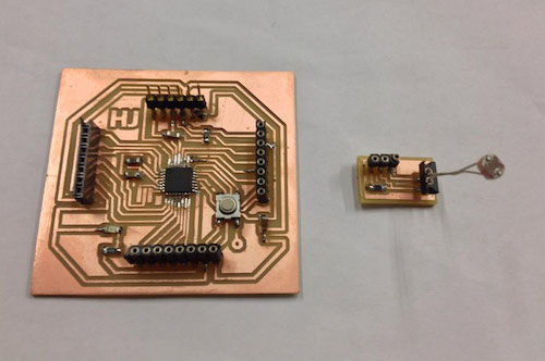
I used my Fabduino that I designed and fabricated earlier during the course. I designed and fabricated a shield with female headers to connect the Photoresistor to Fabduino.
The code:
#include
Servo myservo;
int val;
void setup()
{
myservo.attach(7);
}
void loop()
{
val = analogRead(0);
val = map(val, 1023 , 0, 0, 179);
myservo.write(val);
delay(15);
}
Testing
Unfortunately, the powerful servos that I have ordered earlier did not arrive due to issues with customs. So I had to buy a couple which are powerful enough for the job. The most strongest servos I found have a torque power of 3kg/ cm, I didn't have any other option so I decided to take the risk and buy them and try to minimize the friction as much as possible.
The slots in which the servos will be positioned are customized for the servos I previously ordered, which are bigger in size. When I tried to install the ones I bought, I had a bit of trouble aligning the axes of the servo to the center of rotation of the bottom joint, which resulted in some missalignment that hingered the movement of the shutters.
While testing, I accidentally disattached the FTDI header of my Fabduino while trying to disconnect the cable. I tried to solder it back in place but it did not work out because the copper layer was already disattached. So I had to fabricate, assemble and program a new Fabduino.
Note: Be generous with solder when attaching the FTDI header to the board, the legs of the header are week and very slim so it is important to enforce it with solder. Also, be careful when connecting/ disconnecting the cable as it may get more fragile with time.
I tried hard to tweak/ tune the design to eliminate as much friction as possible. The shutters at this stage hardly fold but do not unfold.
- Conclusion:
Time management is thekey to success! Employ spiral development techniques and avoid demand- side management. Allocate sufficient amount of time for each task and document as you go.
This project is a prototype of the system I had in mind, taking into considertion budget and time constraints. I aim to develop this work further in the near future, adding an LCD display and more input devices to allow the user to easily change and control the actuation modes of the shutters.
Click here to download Rhino Files.
Click here to download Rhino Files.
Click here to download Rhino Files.
