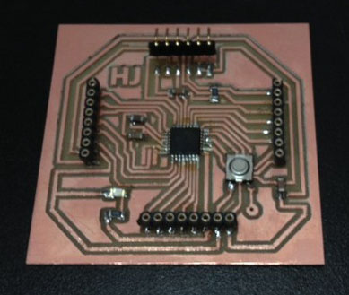
This week, I decided to make my own Fabable Arduino compatible board. This is because it has a stronger microprocessor (atmega 168A) and has more input and output female headers which will save me so much time and effort in the future designing and fabricating man Atiny microcontroller boards.
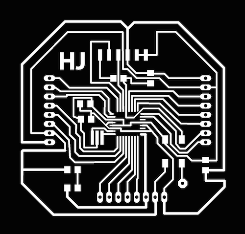
I redesigned the Fabkit board, Fabricated the board, soldered the parts, and burnt the bootloader using FabISP and Arduino IDE.As for the input devices, I used a photoresistor and Fabduino to control a micro servo. And a potentiometer + Fabduino to transmit data (interface) with processing. The code for processing + arduino for the second example is found in the Interface and Applications page.
What I've Learned:
- Try to use thick lines when designing the Fabduino. Thin lines might be too fragile and hard to solder. Tips on soldering SMD microcontrollers are found "here" .
- If a copper trace was removed while milling (especially the traces for the microcontroller), its usually because the lines drawn on eagle are too narrow for the tool. Try to use thicker lines of possible. If its not possible, and the problem occurred after fixing the files, try to perform a micro-surgery where you link the microcontroller pin to the trace with solder.
- After milling, if some traces were not neat, you can use another piece of copper board to sand it the trace flat. Make sure to be gentle when doing this. Consult your tutor.
Code:
#include
Servo myservo;
int val;
void setup()
{
myservo.attach(7);
}
void loop()
{
val = analogRead(0);
val = map(val, 0, 1023, 0, 179);
myservo.write(val);
delay(15);
}
Click here to download Schematic
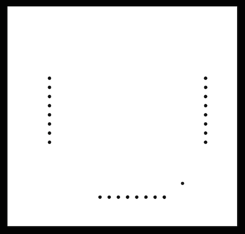
Click here to download Board
