Assignment
Week17: Mechanical Design, Machine Design
Assignment
- group assignment
- design a machine that includes mechanism+actuation+automation
- build the mechanical parts and operate it manually
- document the group project and your individual contribution
Table of content
- Assignment
- My Work
- Group work
- Network - host MQTT configuration
- System context
- Publish musical notes
- Subscribe message and play instrument
- Performance by slide guitar driven by MQTT beat
- Files
- Lessons Learned
- References
My Work
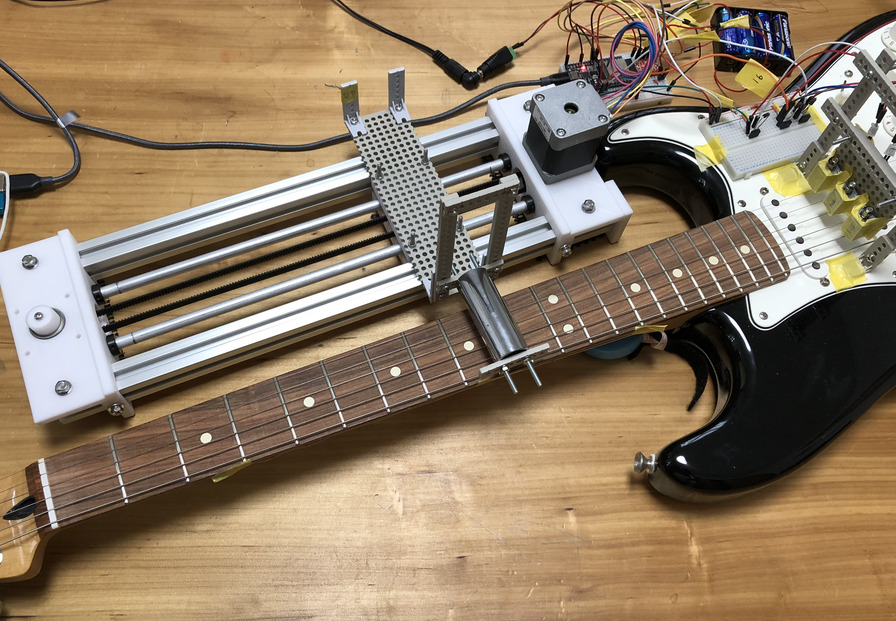
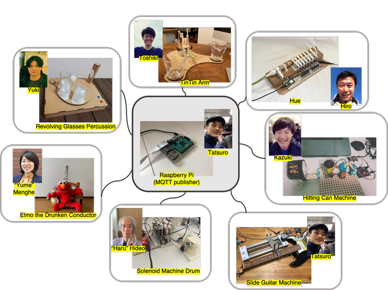
I made slide guitar machine and built system to drive separated instruments at a distanced location. The name of this project is Machine Orchestra at Distant Society (a.k.a. MODS) collaborated by FabAcademy students at Fanlan Kamakura and Kannai.
Group assignment
Summary of group work is written in group assignment page of Fablab Kamakura
Network - host MQTT configuration
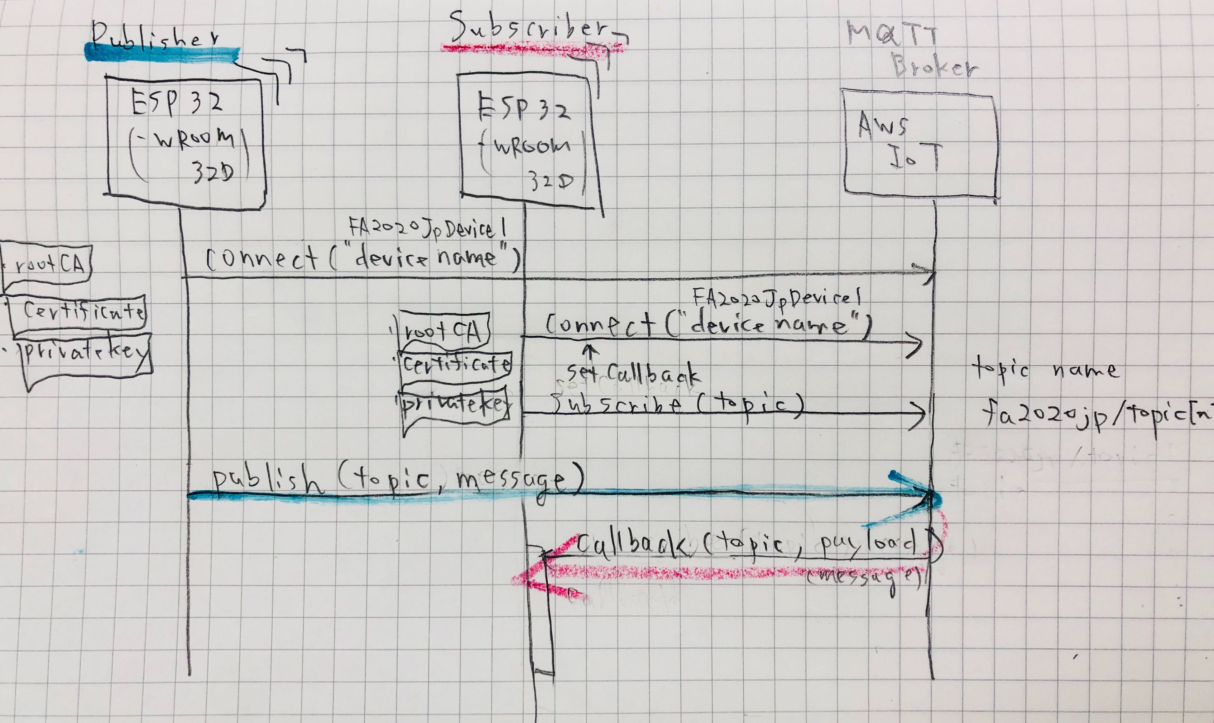
I hosted MQTT broker on AWS IoT and configured things, certification and security, policy.
The purpose of this is benchmarking MQTT for validating configuration, coding and performance. The conclusion of benchmarking is "it's useful and worth using MQTT as a networking infrastructure to make a "distributed musical device" idea, that Japan Fabacademy 2020 students work together for make musical device for each home location and play it together in remote place. This project is for group assignment of mechanical design and machine design week.
I described detail in
- MQTT message publishing/subscribing by Message Broker on AWS IoT in individual page
- client sample code and guideline to connect as a MQTT client in group assignment page for the other students.
System context
As of 21 May 2020
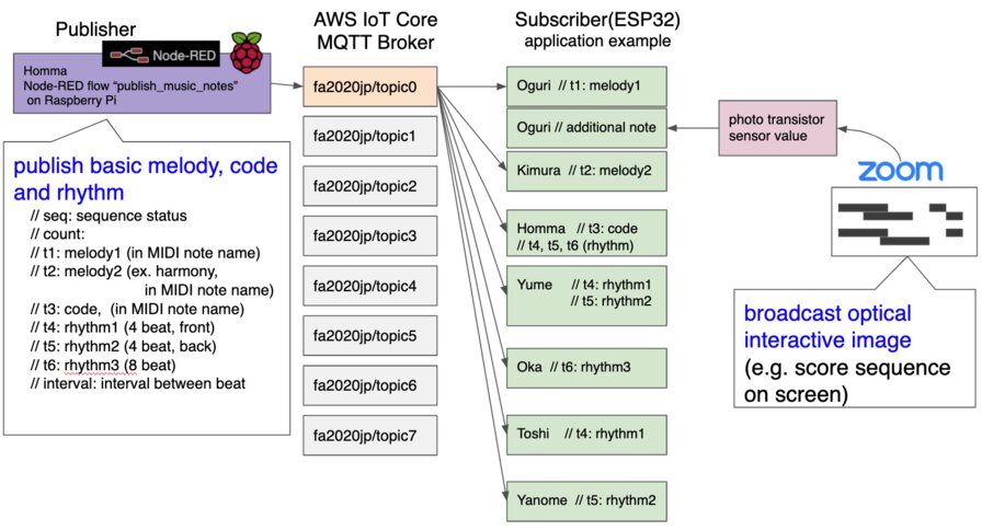
Thorough discussion and experiment in sample code, I roughly designed system context for receiving sound note in remote location.
There are 2 ways to input the sound
- My MQTT client publisher sends values that align with melody, code or rhythm
- From the other location(maybe Oguri-san's locval or hoseted web site) send a image and stream the generative optical image over zoom. Photoresister in local site captures the image and make a note interactively.
As of 26 May 2020
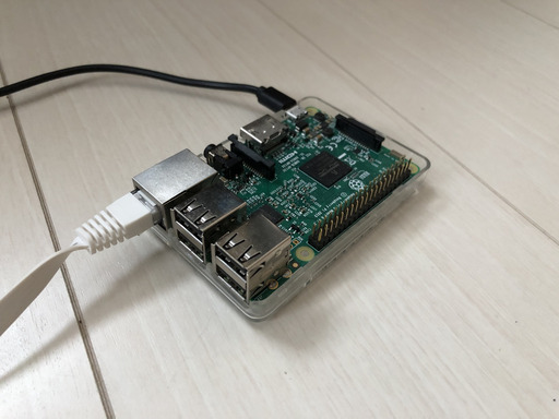
For separating publish and subscribe logic into different board (instead of making delay by publishing logic on receiving logic), I transited publisher process to Node-RED on Raspberry Pi.
As of 1 June
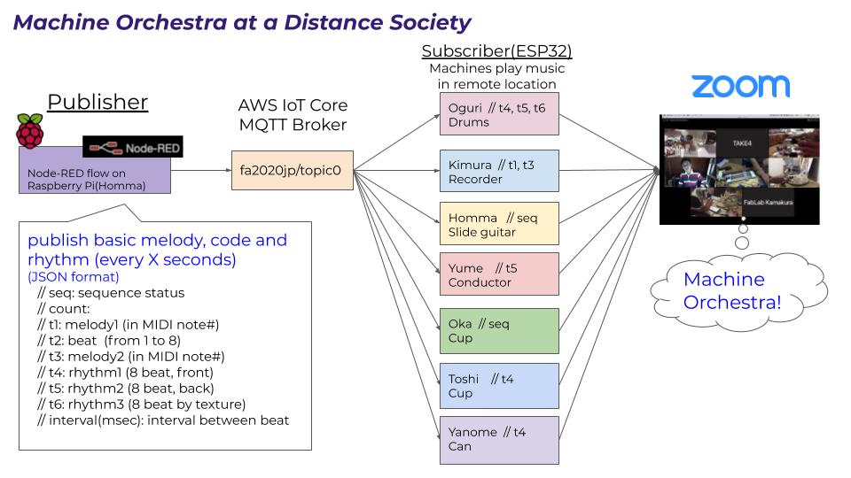
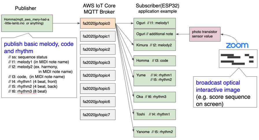
This is final system diagram for playing music. Subscribers decided the element in published messages.
Publish musical notes
As of 21 May 2020
For sending musical note as a publisher, I implemented "Mary had a little lamb" (メリーさんの羊) by arduino code.
mqtt_aws_mary-had-a-little-lamb.ino
I chose this by the reasons for simplicity, length(short song) and copy right.
Key feature in "mqtt_aws_mary-had-a-little-lamb.ino"
Publish to 1 topic every subscriber listen to that topic (broadacast to client). Send 1 sequence number and 6 tracks in 1 message by 60bpm(1 beat per second). Sometime beat will divided into two (120bpm, 1 beat per 0.5 seconds basically).
  // Json Key:
  // ss: sequence status
  // t1: melody1 (in MIDI note name)
  // t2: melody2 (ex. harmony, in MIDI note name)
  // t3: code,  (in MIDI note name)
  // t4: rhythm1 (4 beat, front)
  // t5: rhythm2 (4 beat, back)
  // t6: rhythm3 (8 beat)
Serial monitor output of "mqtt_aws_mary-had-a-little-lamb.ino"
After experiment and discssion with team, I found some idea needs to be changed as follows
- I need to divide input and output devices into two board. It's because there is no room to run callback logic on received message when long sequential publishing logic is running. I will transit the logic into python code and run publisher in raspberry Pi, then make ESP32 as a publisher and musical device controller.
- It's good to publish rhythm in quick tempo (120bpm (1 beat per 0.5 seconds basically)) as solenoid works swiftly.
- It's difficult to publish melody in quick tempo because some mechanical behavior takes time to move and that brings timelug. For avoiding that, It's good to configure code in long span and make room how to behave and make melody line for each local instrument (unless the melody maker works in swiftly like multiple solenoids attached to recorder(笛)..).
As of 26 May 2020
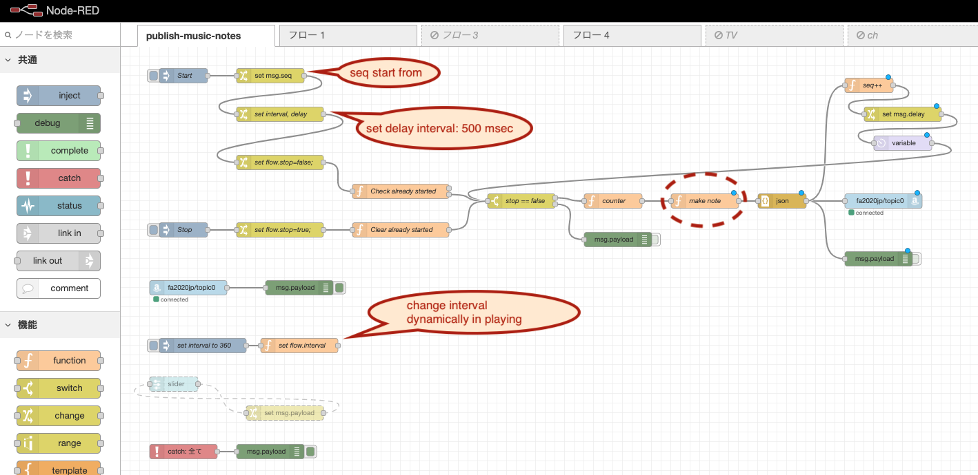 "make note" (function node)
  var interval = msg.delay;
  var seq = msg.seq;

  function makeNotes(t1, t2, t3, t4, t5, t6){
      msg.payload =  {
          "seq":seq,
          "count": msg.count,
          "t1":t1,
          "t2":t2,
          "t3":t3,
          "t4":t4,
          "t5":t5,
          "t6":t6,
          "interval": interval
      }
  }

  var beat = seq % 8;
  switch(beat){
      case 1:
          makeNotes(60, 55, 60, 1, 0, 1); // ド ソ C
          break;
      case 2:
          makeNotes(67, 64, 60, 0, 1, 1); // ソ ミ C
          break;
      case 3:
          makeNotes(64, 60, 60, 1, 0, 0); // ミ ド C
          break;
      case 4:
          makeNotes(71, 55, 60, 0, 1, 1); // シ ソ C
          break;
      case 5:
          makeNotes(67, 60, 60, 1, 0, 0); // ソ ド C
          break;
      case 6:
          makeNotes(69, 64, 60, 0, 1, 1); // ラ ミ  C
          break;
      case 7:
          makeNotes(67, 60, 60, 1, 0, 1); // ソ ド C
          break;
      default:
          makeNotes(64, 60, 60, 0, 1, 0); // ミ ド C
  }

  return msg;
At function node named "make note" on Node-RED, message is constructed for each "beat"(beat sequence that is started from 1 when music is started) (26 May, 2020)
As of 1 June 2020
The Node-RED flow diagram is the same as the version of 26 May.
Node-RED_publish-music-notes_20200601.json
I updated "make note" function note for changing code every 4 messages.
  var interval = msg.delay;
  var seq = msg.seq;

  function makeNotes(t1, t2, t3, t4, t5, t6){
      msg.payload =  {
          "seq":seq,
          "count": msg.count,
          "t1":t1,
          "t2":t2,
          "t3":t3,
          "t4":t4,
          "t5":t5,
          "t6":t6,
          "interval": interval
      }
  }

  function checkNote(note){
      if (note > 72) {
          note = note - 12;
      }
      if (note < 60) {
          note = note + 12;
      }
      return note;
  }

  function melodySequence(seq, t1s) {
      var beat = seq % 8;
      var t1;

      switch(beat){
      case 1:
          //t1 = checkNote();
          makeNotes(t1s, 1, t1s, 1, 0, 1); // ド ソ C
          break;
      case 2:
          t1 = checkNote(t1s + 7);
          makeNotes(t1, 2, t1s, 0, 1, 1); // ソ ミ C
          break;
      case 3:
          t1 = checkNote(t1s + 4);
          makeNotes(t1, 3, t1s, 1, 0, 0); // ミ ド C
          break;
      case 4:
          t1 = checkNote(t1s + 11);
          makeNotes(t1, 4, t1s, 0, 1, 1); // シ ソ C
          break;
      case 5:
          t1 = checkNote(t1s + 7);
          makeNotes(t1, 5, t1s, 1, 0, 0); // ソ ド C
          break;
      case 6:
          t1 = checkNote(t1s + 9);
          makeNotes(t1, 6, t1s, 0, 1, 1); // ラ ミ  C
          break;
      case 7:
          t1 = checkNote(t1s + 7);
          makeNotes(t1, 7, t1s, 1, 0, 1); // ソ ド C
          break;
      default:
          t1 = checkNote(t1s + 4);
          makeNotes(t1, 8, t1s, 0, 1, 0); // ミ ド C
          break;
      }
  }

  var beat = seq % 8;
  switch(1 <= beat && beat <= 4){
      case true:
          melodySequence(seq, 60); // C
          break;
      case false:
          melodySequence(seq, 65);  // F
          break;
  }
  return msg;
For mitigating delay in publishing, I changed the internet connection from Wifi to LAN cable. It would add the stability to the messsaging performance.
As of 3 June 2020 (team presentation at global review)
For collaborative work at presentation, I changed "make note" function note into what Oguri-san provided as a sample. The other part of flow was confirmed to change the interval per message by inject node, start or stop music.
Node-RED_flow_publish-music-notes_20200603_presented.json
Subscribe music and drive devices
Solenoid
Solenoid moves very quickly just by high/low direction in digitalWrite() in arduino code.
Circuit for solenoid
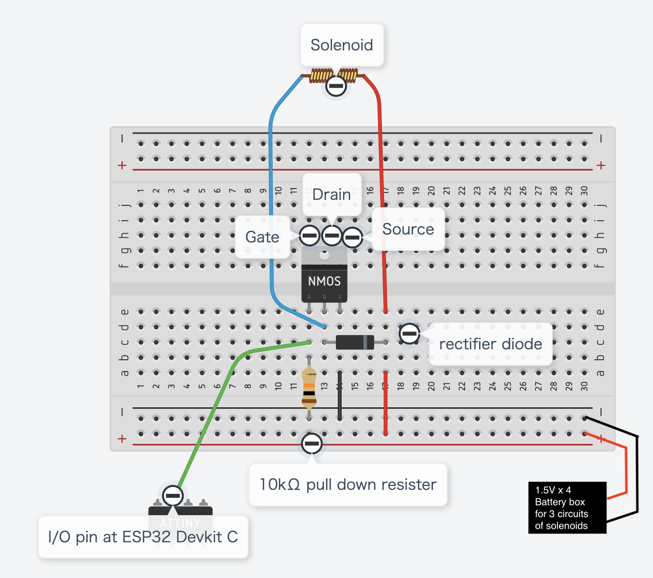
I used 3 set of following materials and connect it to data pins(S1: 4, s2: 16, S3:17) at ESP32 Devkit C in parallel.
| Material | Value | Price | Link |
|---|---|---|---|
| Solenoid 5V ZHO-0420S-05A4.5 Push type | 1.1A by 5V | 450 yen | link |
| Nch Power MOSFET 2SK2232(60V25A) | Driven by 4V | 100 yen | link |
| Generic rectifier diode 1000V1A 1N4007 | 100 yen (20 set) | link |
For supplying sufficient voltage for this circuit (x 3 parallel), I used separated battery box(1.5V x 4).
Ref: a Japanese blog article: ソレノイド(ZHO-0420S-05A4.5)をArduinoとMOSFETで動かしてみた!
(I made left circuit diagram by Tincar CAD)
Example sounds by solenoid
When I subscribed topic on MQTT broker on AWS IoT, received messages per beat and drive multiple solenoid, I found small fluctuation between beats(messages). Following .ino code is sample for people who subscribe MQTT broker and drive their devices.
- v1: sequential delays in 1 beat
- v2: one time delay in 1 beat
- v3: simple son clave for intro and second note joins after 32 beat
- v4: sleep and skip messages then sync
- v5: simple 8 beat
As of 26 May 2020
v1: sequential delays in 1 beat
It's not good idea for MQTT subscriber to delay per multiple devices in 1 beat. This is unti-pattern like:
  digitalWrite(S1, HIGH);
  delay(50);
  digitalWrite(S1, LOW);

  digitalWrite(S2, HIGH);
  delay(50);
  digitalWrite(S2, LOW);
mqtt_aws_music_subscriber_v1.ino
v2: one time delay in 1 beat
Rather than sequential delays is 1 beat like v1, it's good to minimize delay in 1 beat like:
  digitalWrite(S1, HIGH);
  digitalWrite(S1, LOW);
  delay(50);
  digitalWrite(S2, HIGH);
  digitalWrite(S2, LOW);
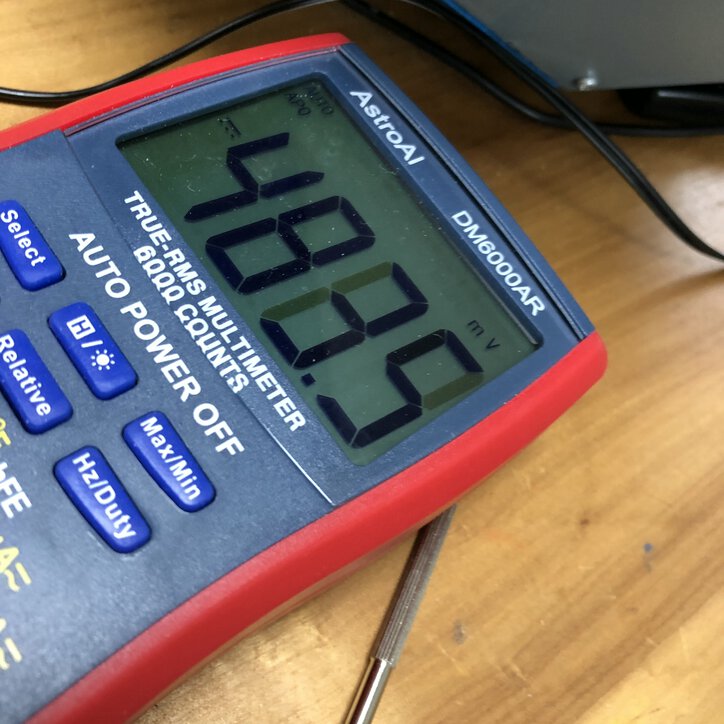
Making multiple device "HIGH" at the same time consumes voltage. It looks not enough to cover 2 solenoids (pushing at the same time) by 5V pin of ESP32 and that brings unstable delay in pusshing timing.
Checking voltage by multimeter when pushing 2 solenoid connecting at the same time, the first solenoid consumes 2.8V to 3.2V and the second solenoid consumes 2.5V. That's why I connected devices to 1.5V x 4 batteries and supplied voltage from that. That looks to bring stability of timing of pushing.
mqtt_aws_music_subscriber_v2.ino
v3: simple son clave for intro and second note joins after 32 beat
For checking the timing to enter to the music, just check sequence number like:
  int seq = doc["seq"].as<int>();
  int interval = doc["interval"].as<int>();
  int overhead; // overhead for each beat (returned by pushSolenoids())
  int t5 = doc["t5"].as<int>();
  int t6 = doc["t6"].as<int>();

  if (seq < 32 ){ // until reaching to seq:32, just make sound in the t6 track
    switch (seq % 8) {
        // case 2:
        //  ***
            delay(interval / 2 ); // for t6, delay half beat (subtracted delay time by former track of t5, like "son clabe")
            pushSolenoids(0, 0, t6); // on t6 beat after delay half beat
            break;
        default:
            pushSolenoids(0, 0, t6); // on t6 beat after delay half beat
    }
  } else { // from reaching to seq:32, the other t5 track joins with syncing the timing.
    switch (seq % 8) {
        case 2:
            overhead = pushSolenoids(0, t5, 0); // on t6 beat after delay half beat
            delay(interval / 2 - overhead); // for t6, delay half beat (subtracted delay time by former track of t5, like "son clabe")
            pushSolenoids(0, 0, t6); // on t6 beat after delay half beat
            break;
        default:
            pushSolenoids(0, t5, t6); // on t6 beat after delay half beat

    }
  }
mqtt_aws_music_subscriber_v3.ino
v4: sleep and skip messages then sync
For many devices like servo motor or stepping motor that take longer time than 1 beat (default: 500msec in this case), it's necessary to skip the messages during the device is working and sync again after the device finish working.
It's good to keep minimizing the logic payload of function of mqttCallback on received message. It's because callback process is run on the same thread of ESP32 (that does not support multi thread programming). If you need to run longer period than the next message comes, you should check sequence number and skip the messages considering the working duration of local machine. Or, you can communicate to the other board and separate the longer process for machine behavior to the different microcontroller.
    // Sample for waiting until the machine behavior finishes
    int beat = seq % 16;
    if (beat == 1 ){  // only run 1 beat in 8 beat.

        // write logic for spinning motor etc. ---
        // ex. spining servo 180 degree
        pushSolenoids(t4, 0, 0); // on t6 beat after delay half beat
        sleep(3);
        // -- end --
    } else if (beat == 9 ){
        pushSolenoids(0, t5, 0);

        // write logic for spinning motor etc.
        // ex. spining servo -180 degree
        pushSolenoids(t4, 0, 0); // on t6 beat after delay half beat
        sleep(3);
        // -- end --
    }
mqtt_aws_music_subscriber_v4.ino
v5: simple 8 beat only using sequence number
If pattern is simpoly fixed and there is no need to trigerred by message in track, you can use just sequence number and drive devices like:
  switch (seq % 4) {
    case 1:
        pushSolenoids(1, 0, 0);
        break;
    case 3:
        pushSolenoids(0, 0, 1);
        break;
    default:
        pushSolenoids(0, 1, 0);
  }
mqtt_aws_music_subscriber_v5.ino
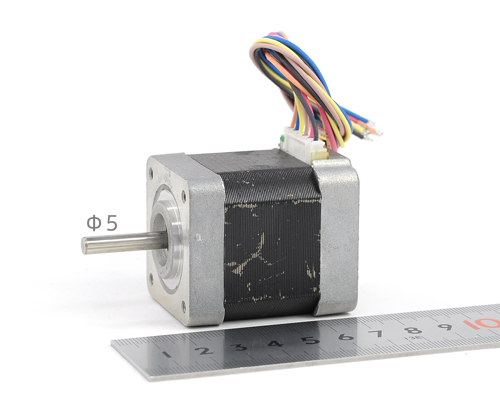
Stepping motor
I decided to use a stepping motor and a motor driver for moving arm that attaches "bottleneck" to touch with guitar string.
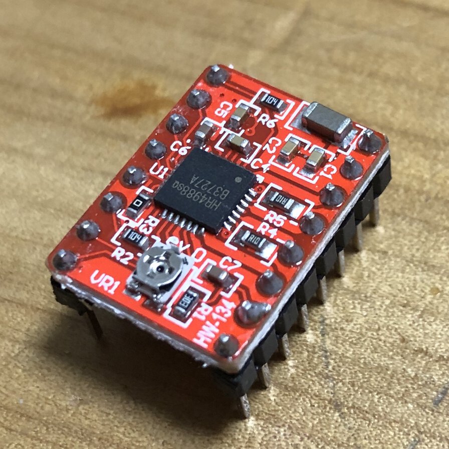
I checked tutorial on reference site of vendor(Original Mind) or an article in lastminutengineers.com and confirmed the connection.

Connection between A4988 motor driver and motor cables (from Original Mind) is like this.
- 2B - black
- 2A - brown
- 1A - yellow
- 1B - orange
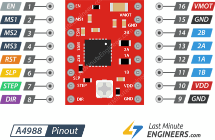
Pinmap of A4988 (from lastminutengineers.com) is like this.
I used pins of:
- VMOT - 12V AC Adapter (AC adapter supply voltage by 12V - max 1.2A)
- GND - AC Adapter(Ground)
- 2B - black cable of stepping motor
- 2A - brown cable of stepping motor
- 1A - yellow cable of stepping motor
- 1B - orange cable of stepping motor
- VDD - 5V VCC of ESP32(to control SETP/DIR pin)
- GND - GND of ESP32
- SETP - 25 IO pin of ESP32
- DIR - 26 IO pin of ESP32
After I changed the 12V AC Adapter that has current output of 1.5A (original one was of 1.2A), the motor did not work concisely. Dir pin seems not work or sometime motor stops after few seconds work. I turned back to 12V, 1.2A AC adapter but that did not solve the problem. I checked this with Tamiya-san and did limit current by adjusting A4988 screw type potentiometer.
Seeing a tutorial about A4988, I limit the maximum amount of current flowing through the stepper coils and prevent it from exceeding the motor's rated current.
Imax=Vref/0.4 means Vref=Imax*0.4=1.2*0.4=0.48V
So I adjusted tiny screw and found the point that the voltage between the potentiometer and ground-pin near 0.48V. This works and the stepping motor finely.
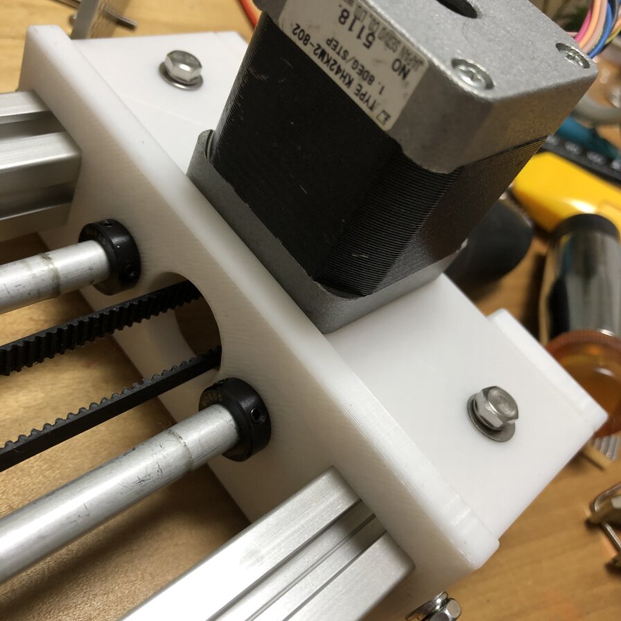
Checking a datasheet of KH42KM2-802, that says Current A/Phase 0.4A. So I tried Vref=Imax*0.4=0.4*0.4=0.16V. I tried this but 0.16V causes strange noise in the stepping motor. As Vref=0.25V works without noise, I finally used that by adjusting the steppig motore.
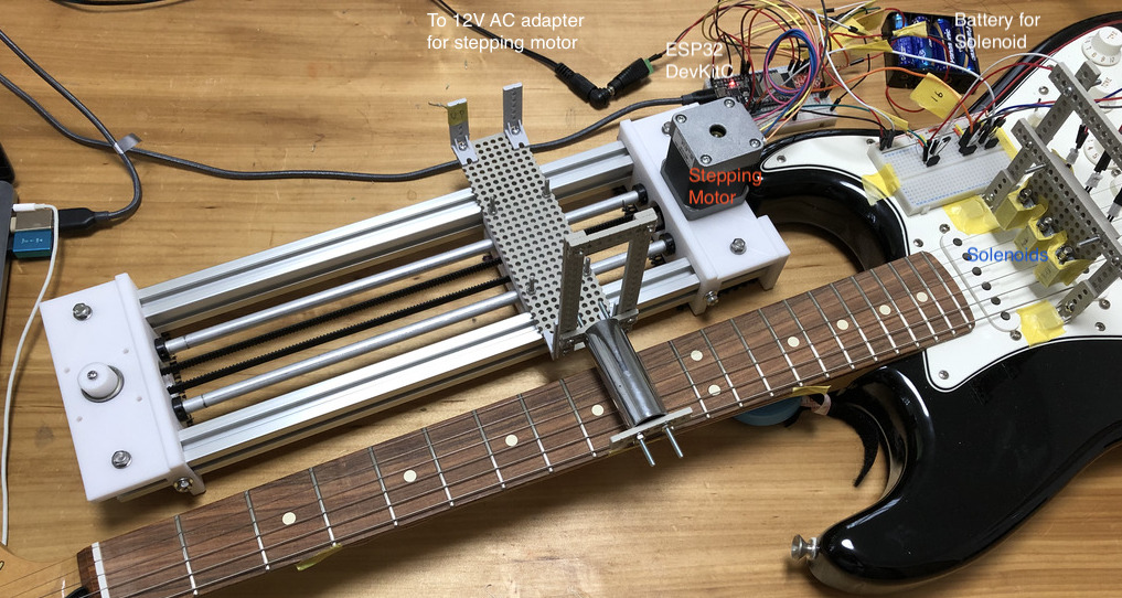
Design of slide guitar machine
3D Design
With help of my instructor Tamiya-san, I got a concept to use stepping motor to slide the arm along with the neck of guitar.
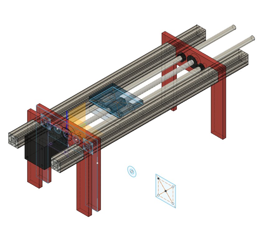
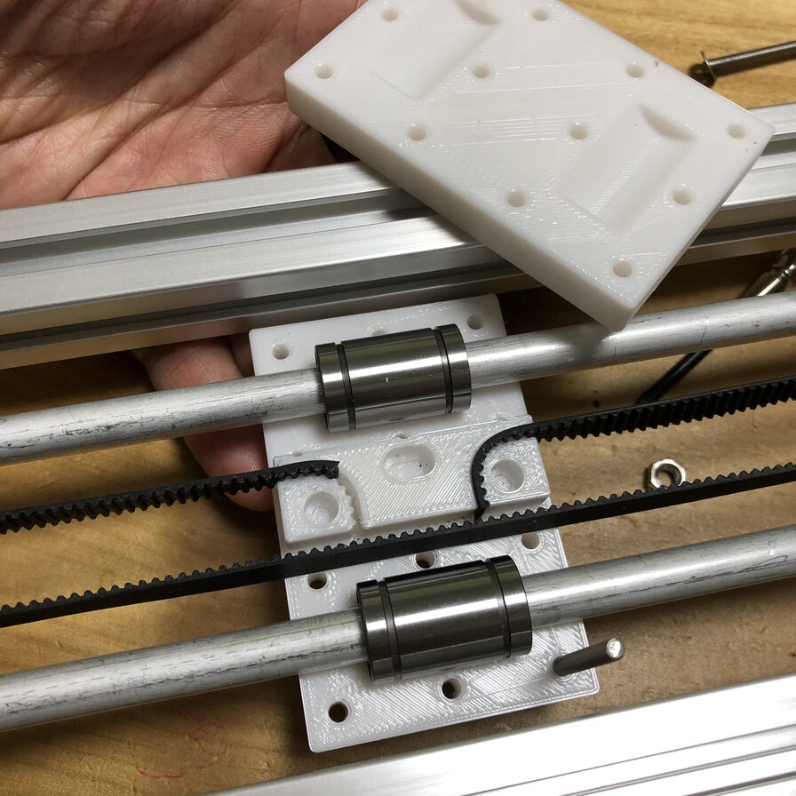
Updated idea (arm laying along with guitar neck)
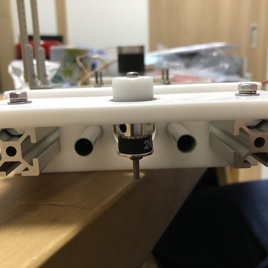
For making the base of arm stable, I changed the design of the machine.
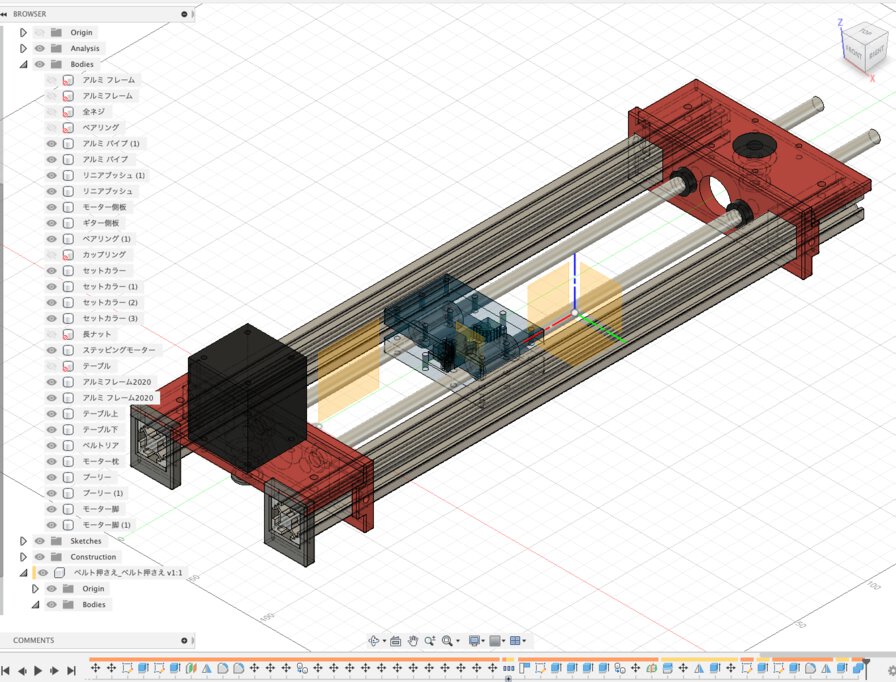
Also, I changed to attach screw as a central axis into belt and pooley for increasing moving speed of code change performance of slide guitar.
Design file by Fusion360(A360)
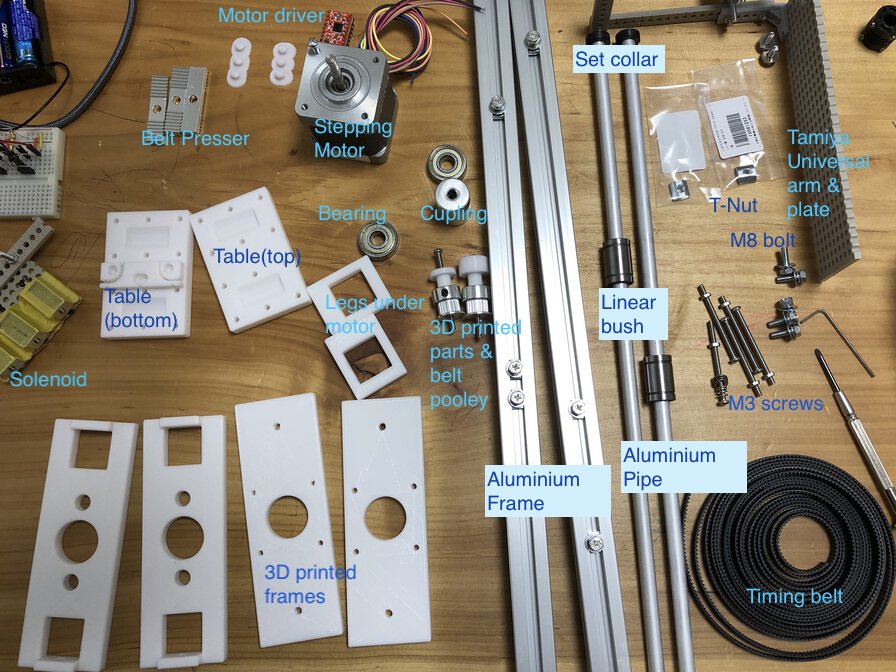
Bill of materials
| Material | Material(Japanese) | Size | #(Rod design) | #(Belt design) | Unit price | Link | Amount | Ref: | |
|---|---|---|---|---|---|---|---|---|---|
| Aluminum frame | アルミフレーム | 2020_L400 | 2 | 2 | 206 | link | 412 | link | |
| T nat SS | TナットSS | M4 | 6 | 8 | 39 | link | 234 | for fixing aluminum frame and 3D printed parts | |
| Bolt | ボルト | M4 | 6 | 8 | 8 | link | 48 | for fixing aluinium frame and 3D printed parts | |
| Linear bush | リニアブッシュ | Φ8_Φ15_24 | 2 | 2 | 279 | link | 558 | ||
| Aluminum pipe | アルミパイプ | Φ8_395 | 2 | 2 | 119 | link | 238 | ||
| Set collar | セットカラー | Φ8 | 4 | 4 | 109 | link | 436 | ||
| Threaded rod | 寸切り(全ネジ) | M8_285 | 1 | 0 | 38 | link | 38 | ||
| T-Nut | Tナット | M8_30 | 1 | 0 | 87 | link | 87 | ||
| Bearing | ベアリング | Φ8_Φ22_7 | 2 | 1 | 83 | link | 166 | ||
| Stepping motor | ステッピングモーター | Φ5_12V | 1 | 1 | 680 | link | 680 | link | |
| Cupling | カップリング | Φ8-Φ5 | 1 | 0 | 539 | link | 539 | ||
| Motor driver | モータドライバ | A4988 | 1 | 1 | 920 | link | 920 | 5 pieces in 1 set | |
| M3 Screw set(Tamiya) | M3 Screw set | M3_10 | 4 | 4 | 220 | link | 220 | (6mm, 10mm, 15mm, 20mm, 27mm) x 10 set, 10mm for fixing stepping motor | |
| AC adaptor | 電源 | 12V | 1 | 1 | |||||
| Adaptor conversion plug | 電源アダプタ変換プラグ | 5.5mm x 2.1mm DC 12V | 1 | 1 | 699 | link | 699 | Make and female x 10 in 1 set | |
| Screw set(screw+washer+nut) | ネジセット(ネジ+ワッシャー+ナット) | M3_15 | 4 | 4 | 399 | link | 399 | 36 parts in 1 set (to fix anything) | |
| 3D printed parts | 3Dプリントパーツ | 1 | 1 | Tamiya-san sent for me | |||||
| Screw | ネジ | M4_12 | 0 | 0 | Tamiya-san sent to me | 8 | |||
| Timing belt | タイミングベルト | 0 | 1 | 799 | link | 799 | 5m, hole diameter 5mm / Tamiya-san sent to me | 1 | |
| Belt pooley | ベルトプーリー | 0 | 2 | (set by timing belt) | link | (set by timing belt) | Tamiya-san sent to me | 2 | |
| Belt presser (metal) | ベルト押さえ(金属) | 0 | 0 | Tamiya-san sent to me | 3 | ||||
| Screw | ネジ | M3_45 | 0 | 1 | Tamiya-san sent to me, for fixing belt pooley and bearing | 12 | |||
| Nut | ナット | M3 | 12 | 12 | Tamiya-san sent to me, for fixing slide guitar arm | 12 | |||
| Spring washer | スプリングワッシャー | M3 | 0 | 0 | Tamiya-san sent to me | 4 | |||
| Washer | ワッシャー | M3 | 0 | 0 | Tamiya-san sent to me | 4 | |||
| Cupling (Aluminium) | カップリング(アルミ) | Φ8-Φ5 | 0 | 0 | Tamiya-san sent to me | 1 | |||
| Tamiya universal plate | タミヤ ユニバーサルプレート(L) | 1 | 1 | 726 | 660 | slide guitar table, solenoid attachment | |||
| Tamiya universal arm set long | タミヤ ユニバーサルアーム(ロング) | 1 | 1 | 396 | link | 396 | slide guitar table, solenoid attachment | ||
| Tamiya screw set(30, 40, 50) | TAMIYA 3mmネジセット (30、40、50mm) | 50mm | 4 | 4 | 330 | link | 330 | 30, 40, 50mm x 6 set |
Making slide guitar machine
Assembling
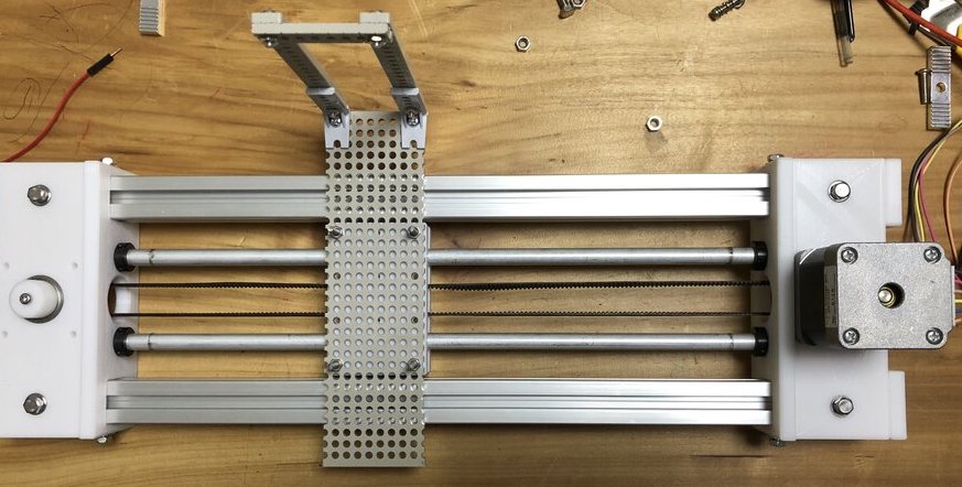
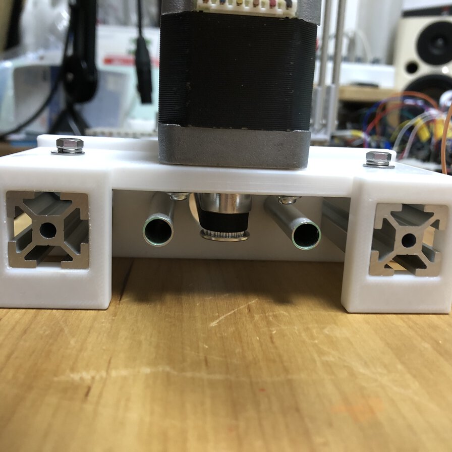
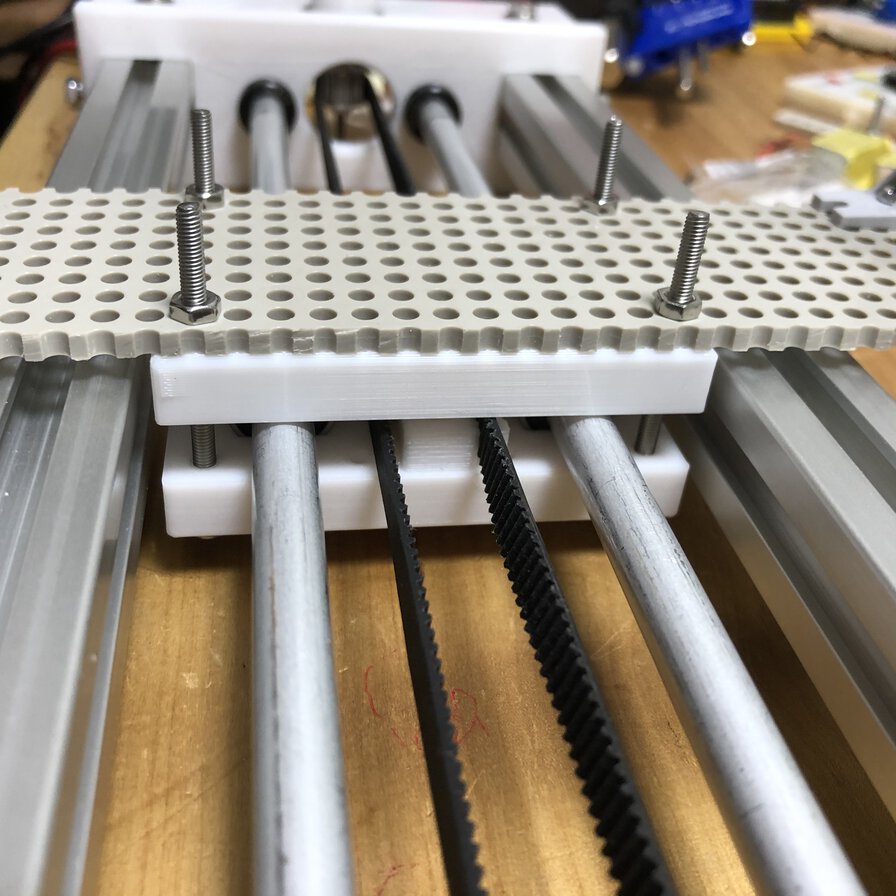
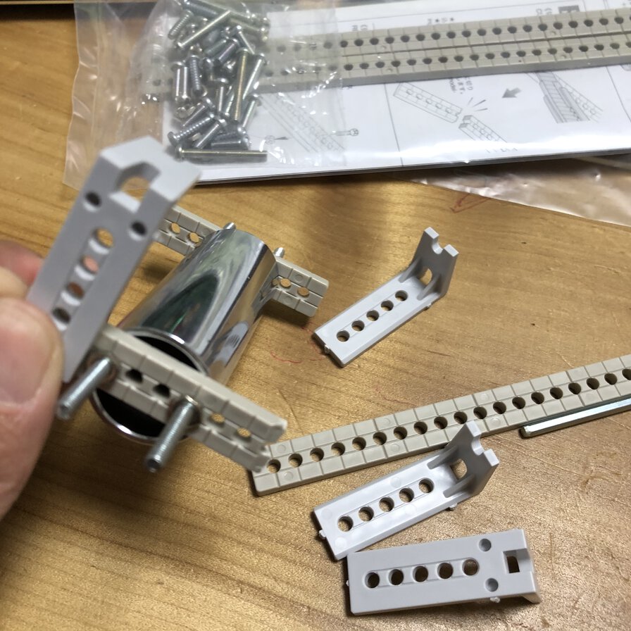
It's important to tighten right belt in these pictures without touching other materials.
Belt presser parts is originally from shared material.
I splitted components of it and expanded the size, embed it into table design. Table design is for attaching to TAMIYA universal plate that has 3mm hole with 5mm spaces.
It's difficult to insert belt to 3D printed parts as the slit is very narrow. I needed to hit the belt from top by rubber mallet to settle the belt in slit of the parts.
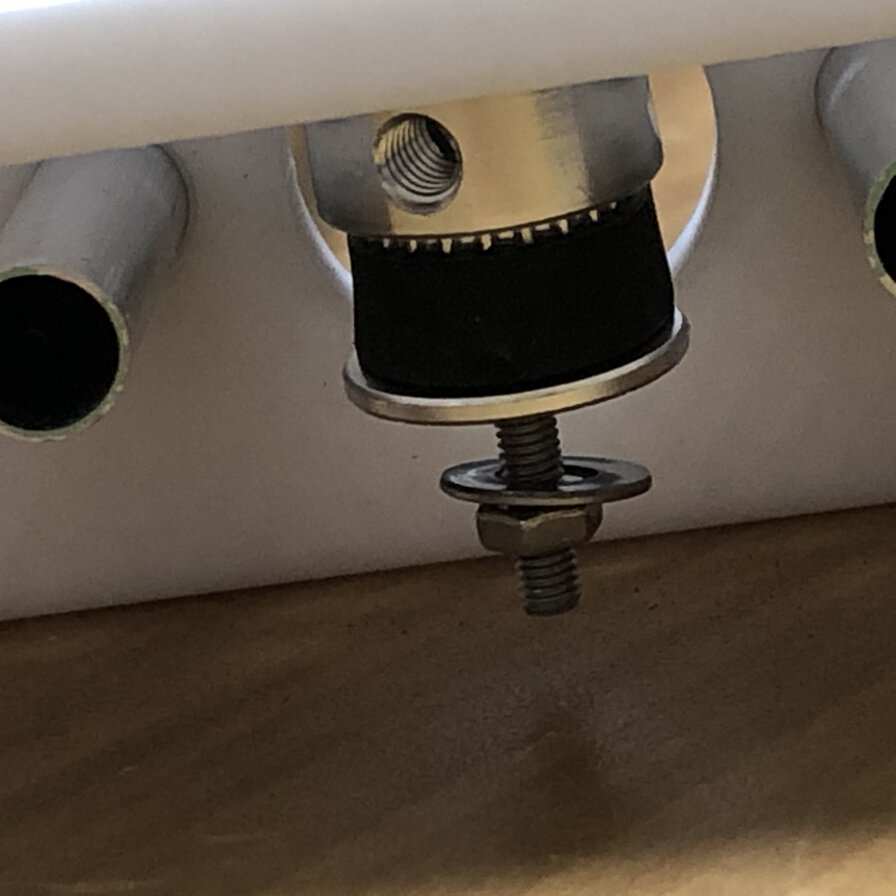
Through experiment, I occasionally needed to check if nut under belt pooley in bearing side is loosened. As the screw is tightly pulled by belt and idle spinning of belt applys pressure to pooley, this nut is loosened and it brings belt touch to the other materials. All that process cause unexpected behavior of moving table. So, I checked this part time by time to make the machine stable.
For the part of attachment of actuator like solenoids or bottleneck of slide guitar, I used "universal arm" of toy kit by TAMIYA INC, a hobby kit company in Japan.
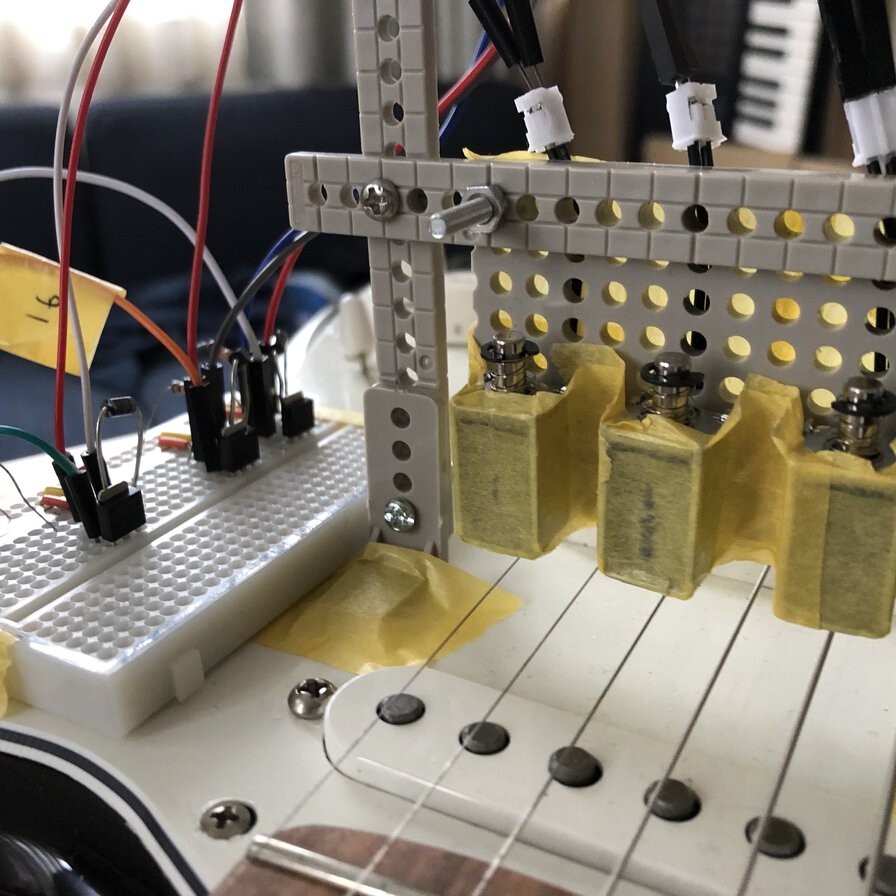
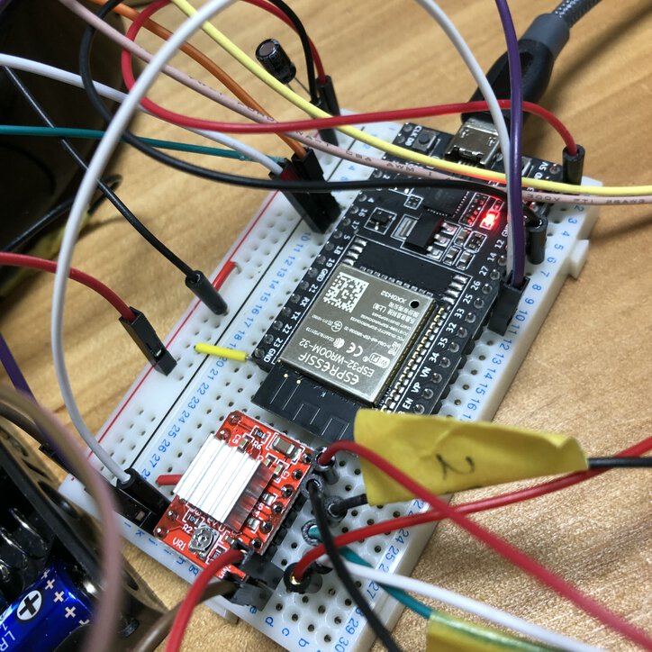
I attached 3 solenoids to 1st, 3rd and 5th string of guitar.
Here is the connection.
As I did not have access to lab at all, I used ESP32 DevKitC as a board that controls 3 solenoids, one stepping motor and connect to Wifi network as a MQTT client.
Making slide guitar machine (timelapsse)
Software
I tweaked my client software embedded to ESP32 to control devices and network communication.
For driving stepping motor by ESP32, I referred "SpoturDeal/ESP32Stepper" library. As that code is for web-based interaface to drive stepping motor from browser, I shaped out necessary parts of codebase and amended it for playing guitar.
mqtt_aws_music_mods_sample_v1_01.ino
Performance by slide guitar driven by MQTT beat
Lessons Learned
- It was fun for playing music with the other students by making skills and IoT technology in separated place. Collaborative work was tough (in terms of architecture organizing serparated machines, software library distribution, musical performance and leadership) but worth trying.
- What I could not do in this project was enriching musical performance. It would be better to make separated microcontrollers for "hands" of left and right. It would bring more swift and effective play on slide guitar.
- Internet connection over Wifi network occurs delay to communicate MQTT message. It will be good to connect machines by LAN cable. The other idea is that separate quick rhythm sequence device from subscriber.
- The most big delay would happen by Zoom meeting system and we could find the other system for real time music session.
Files
- 3D desing of Slide guitar machine : Link to Autodesk360, f3d
- Node-RED_flow_publish-music-notes_20200603_presented.json
- mqtt_aws_music_mods_sample_v1_01.ino
References
- Machine Orchestra at Distant Society (MODS)
- Global presentation video (our performance starts at 1:11:45)
- client sample code and guideline to connect as a MQTT client in group assignment page
- MIT - Machine that makes project
- Jakeread, machineweek-2019 gitlab repository
- ソレノイド(ZHO-0420S-05A4.5)をArduinoとMOSFETで動かしてみた!
- Control Stepper Motor with A4988 Driver Module & Arduino
- Pololu - Schematic diagram of the A4988 stepper motor driver carrier.
- KH42KM2-802 datesheet
- バンドの遠隔同時演奏を生配信する方法
- Youtube: Squarepusher × Z-MACHINE
- Youtube: Gamelan(Indonesia)