Introduction
This weeks assignment was to redraw the echo hello-world board, add (at least) a button and LED (with current-limiting resistor) check the design rules, make it, and test it we have Two main assignments:
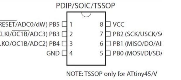
The first step was to check out the pinout for the ATtiny 85 which was the chip i was going to use for the hello world board. After understanding its pins I then went about to design the actual board.
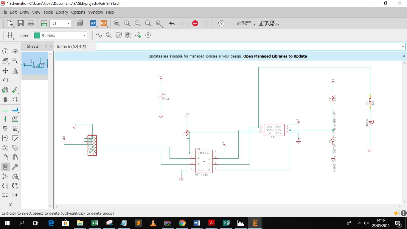
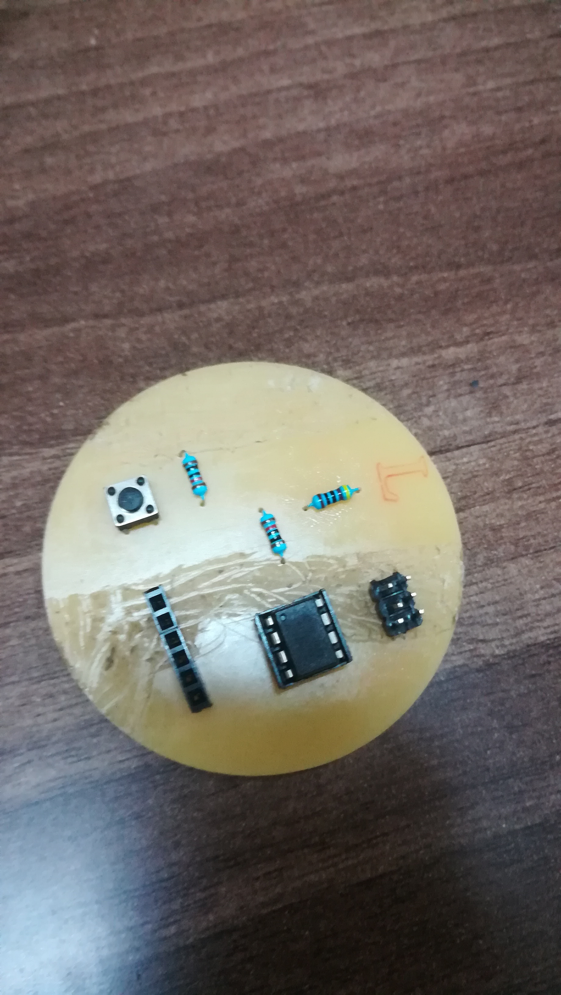
I added all the parts i was gong to use for the board which included:
A buuton
ATtiny 85
2 x 10k resistor
499 ohm resistor
10uf Capacitor
LED
header pins
The completed circuit diagram is as shown below
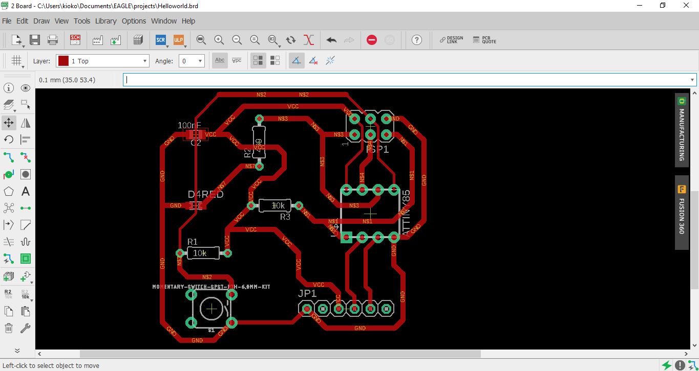
The next step was to manual route my board as it is more efficient, i moved to the board interface for Eagle and generated the tracts for each part as preffered, my final layout is as shown below
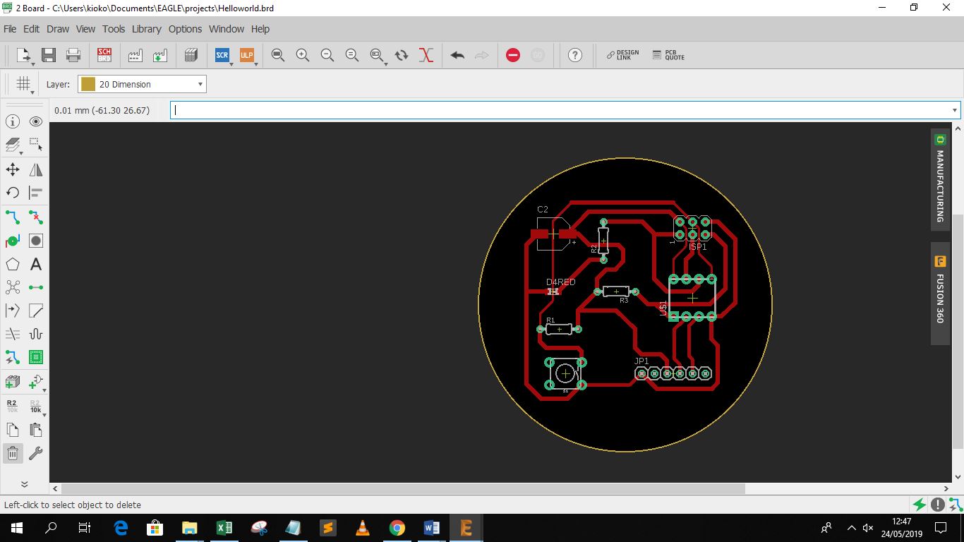
I decided to give my board a unique shap therefore I drew a circle arround it as the putside dimension and then deleted the outside boundaries.
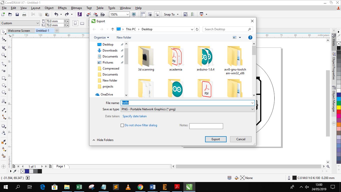
Since achieving the correct scale for the board when importing using png in eagle is hard, I selected the print to pdf command and printed the circuit with the layers required turned on. I then imported the PDF to corel draw and exported the png to accurate dimensions.
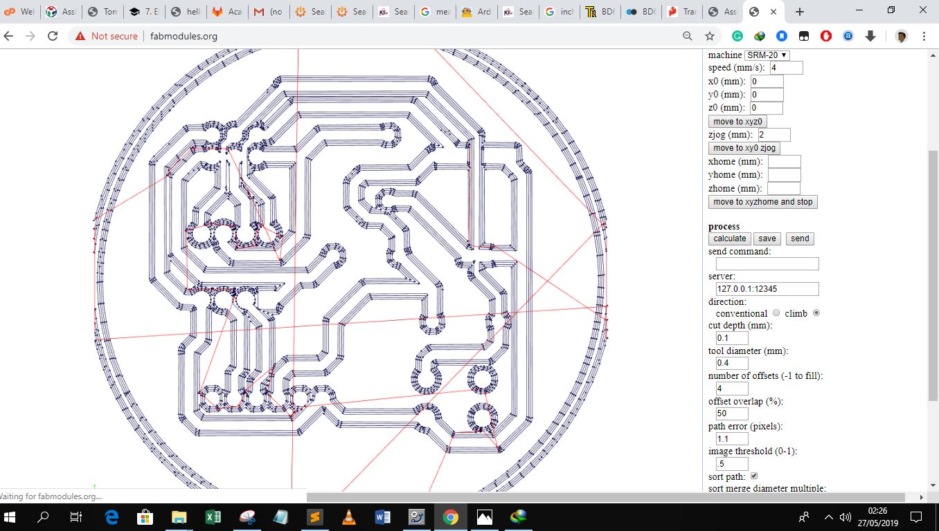
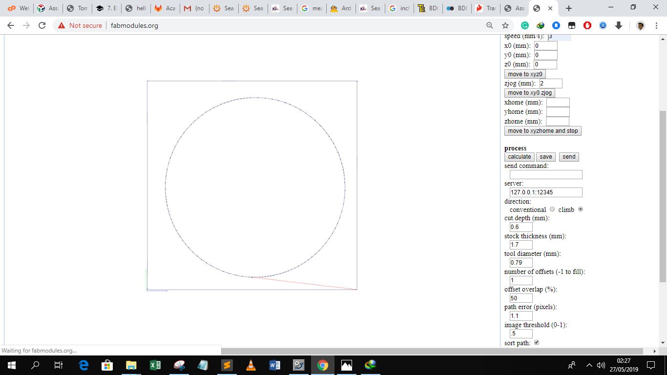
The next step involved generating the cam files using the fab modules, the first png upload was for the tracts and the other for the outline of the board.
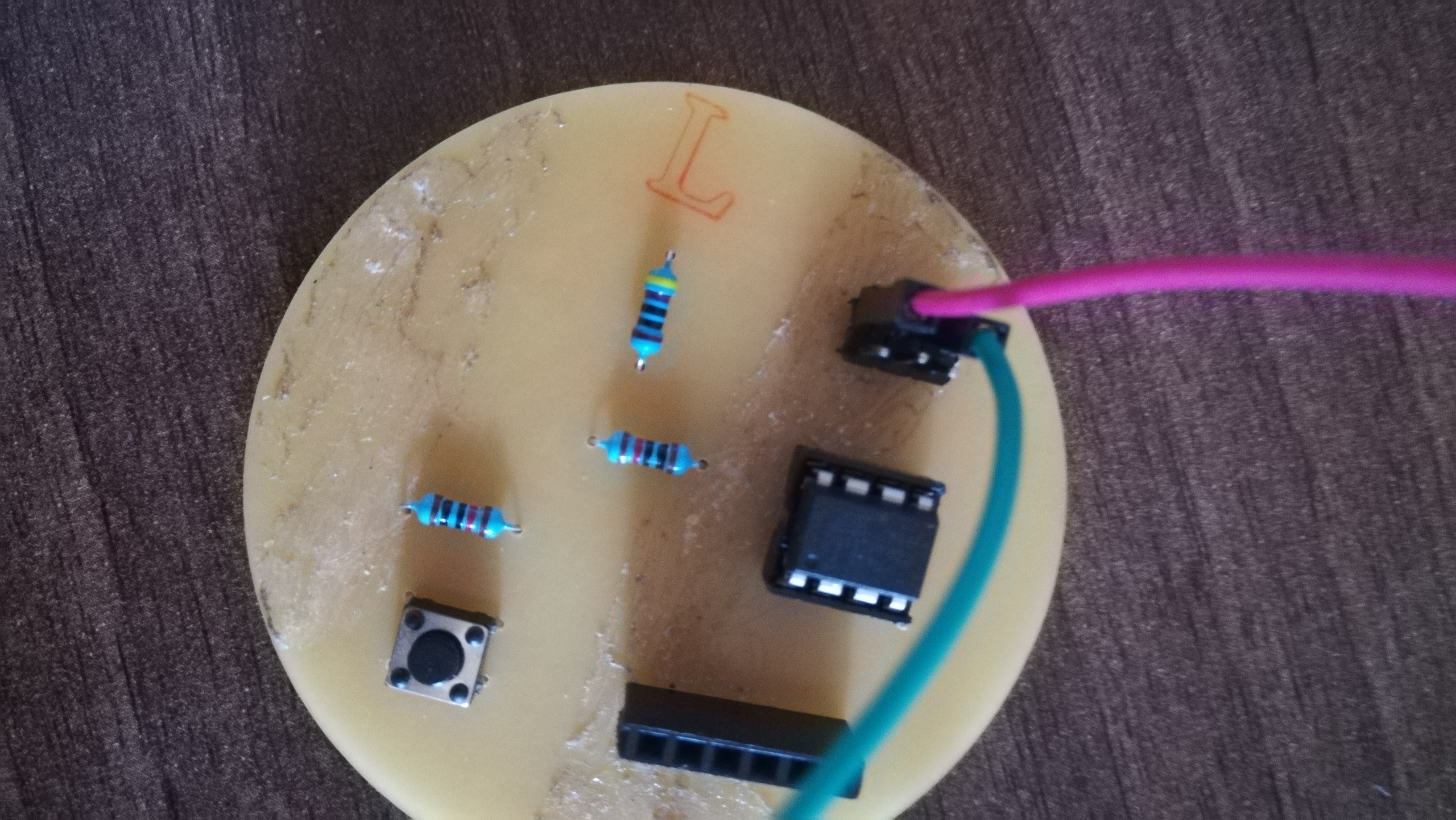
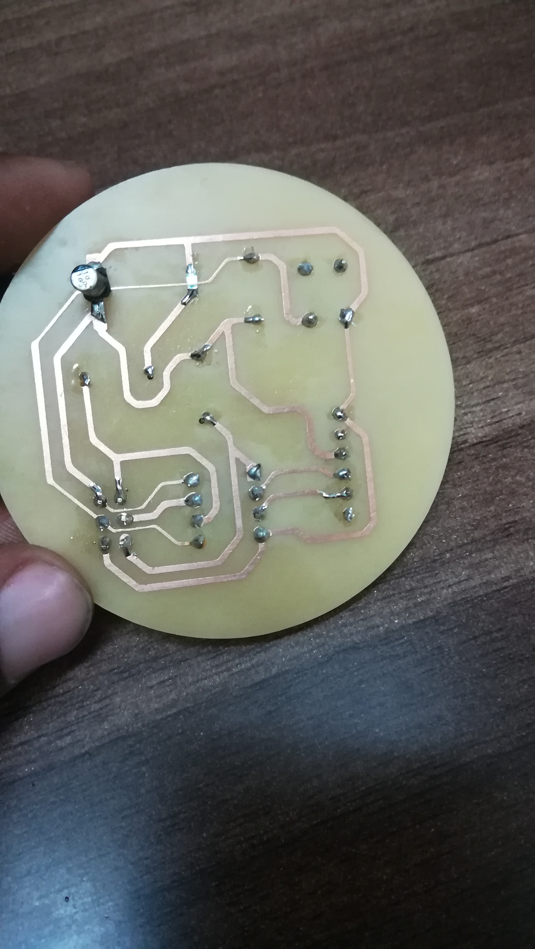
I assembled the components and soldered them as per my design
After soldering i connected my board to the programmer I designed in WEEK 5 then upploaded the code
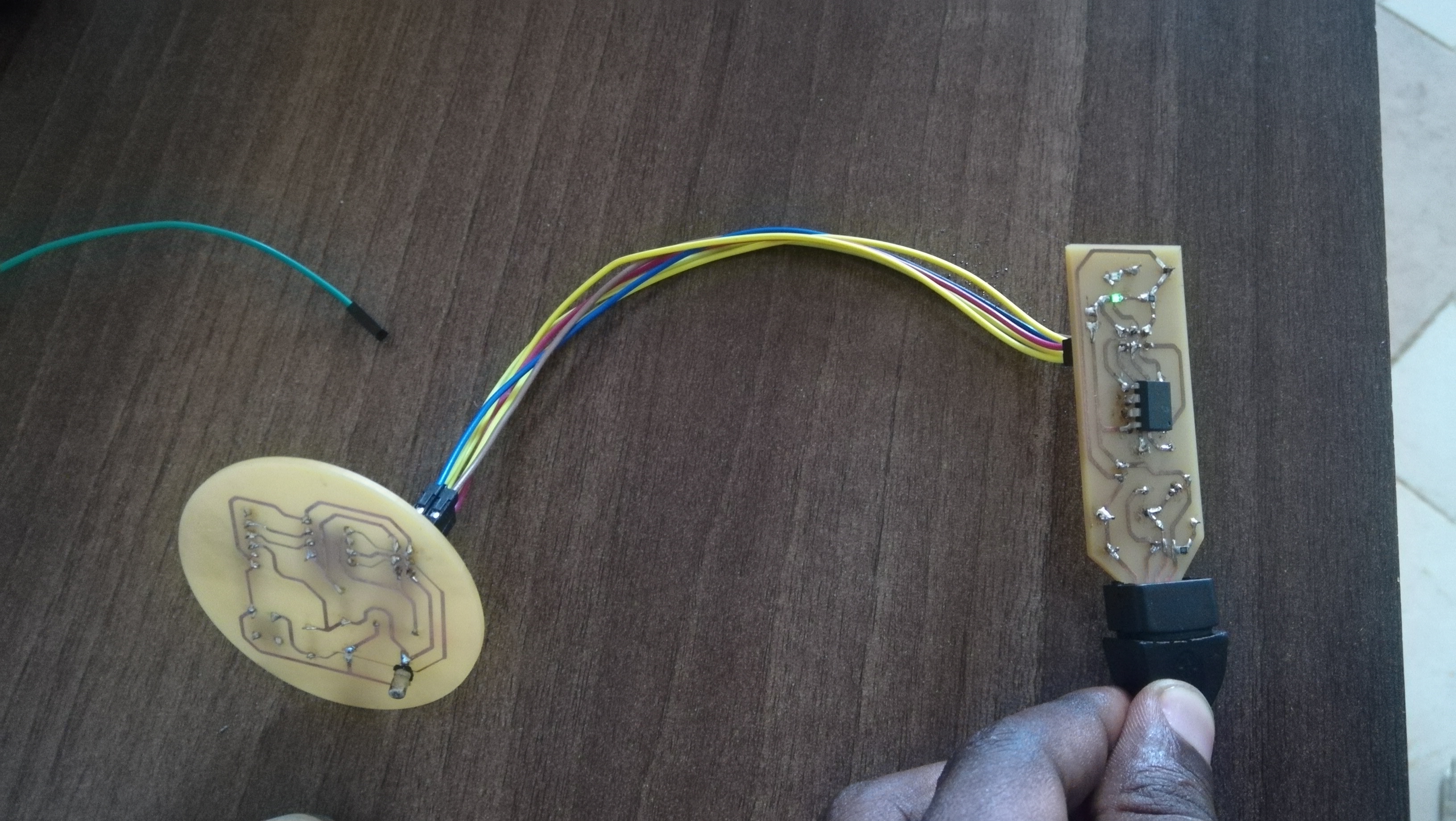
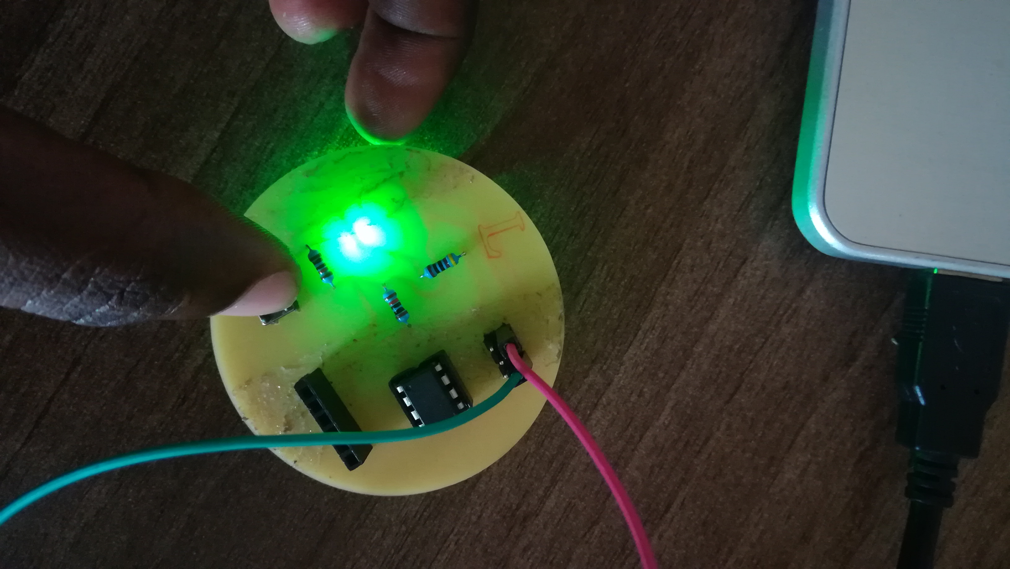
I then tested my board seperately with a connected vcc and ground and it worked out well when I pressed the button