Introduction
This week we have Two main assignments:
3D print something and 3D scan something
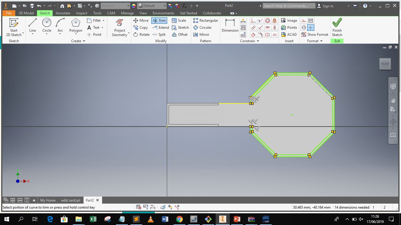
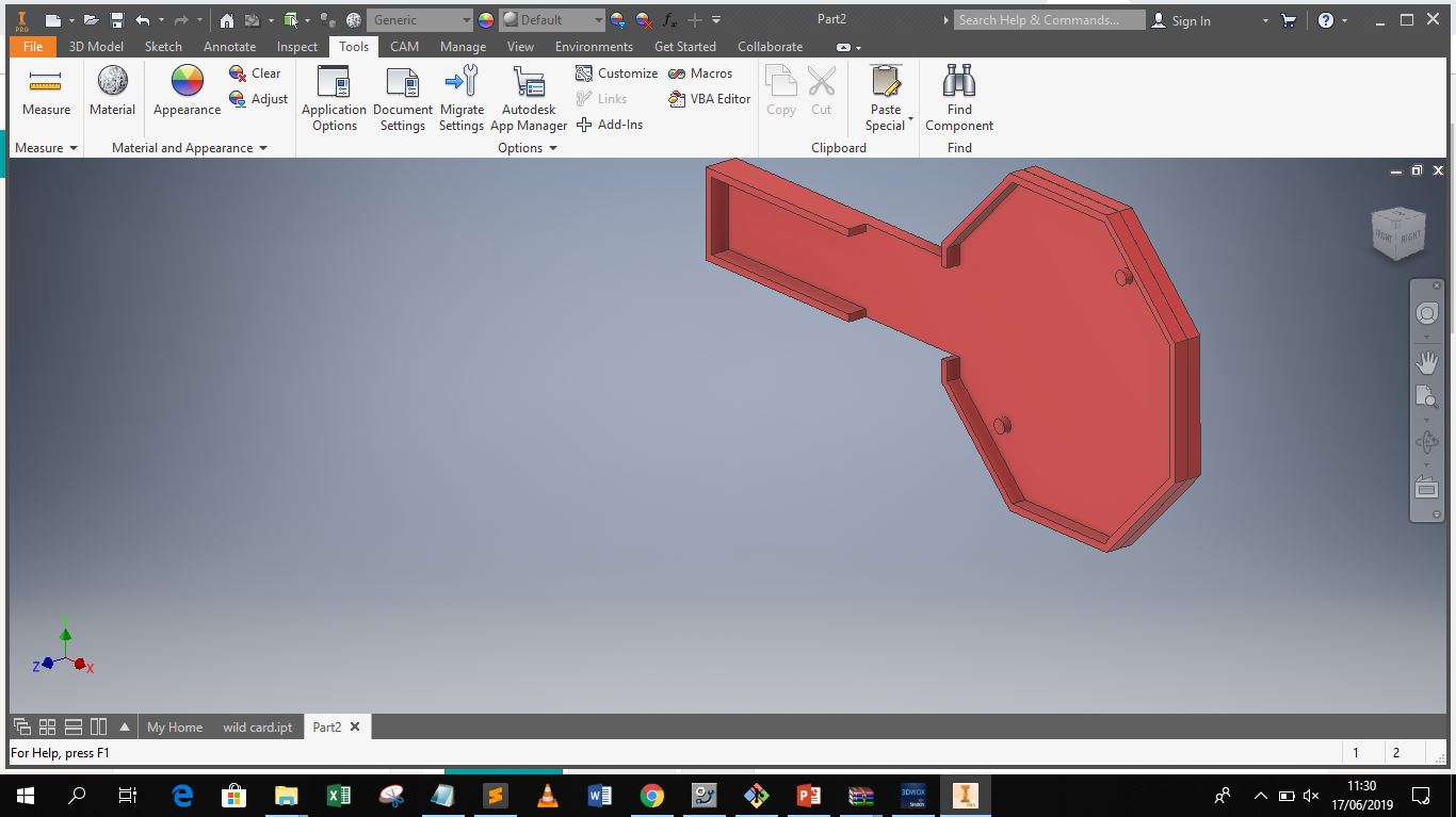
For this assignment I designed my circuit holder for my project. The circuit holder will hold th cicuit designed and produced in the output devices week. My design software of choice is Autodesk Inventor.
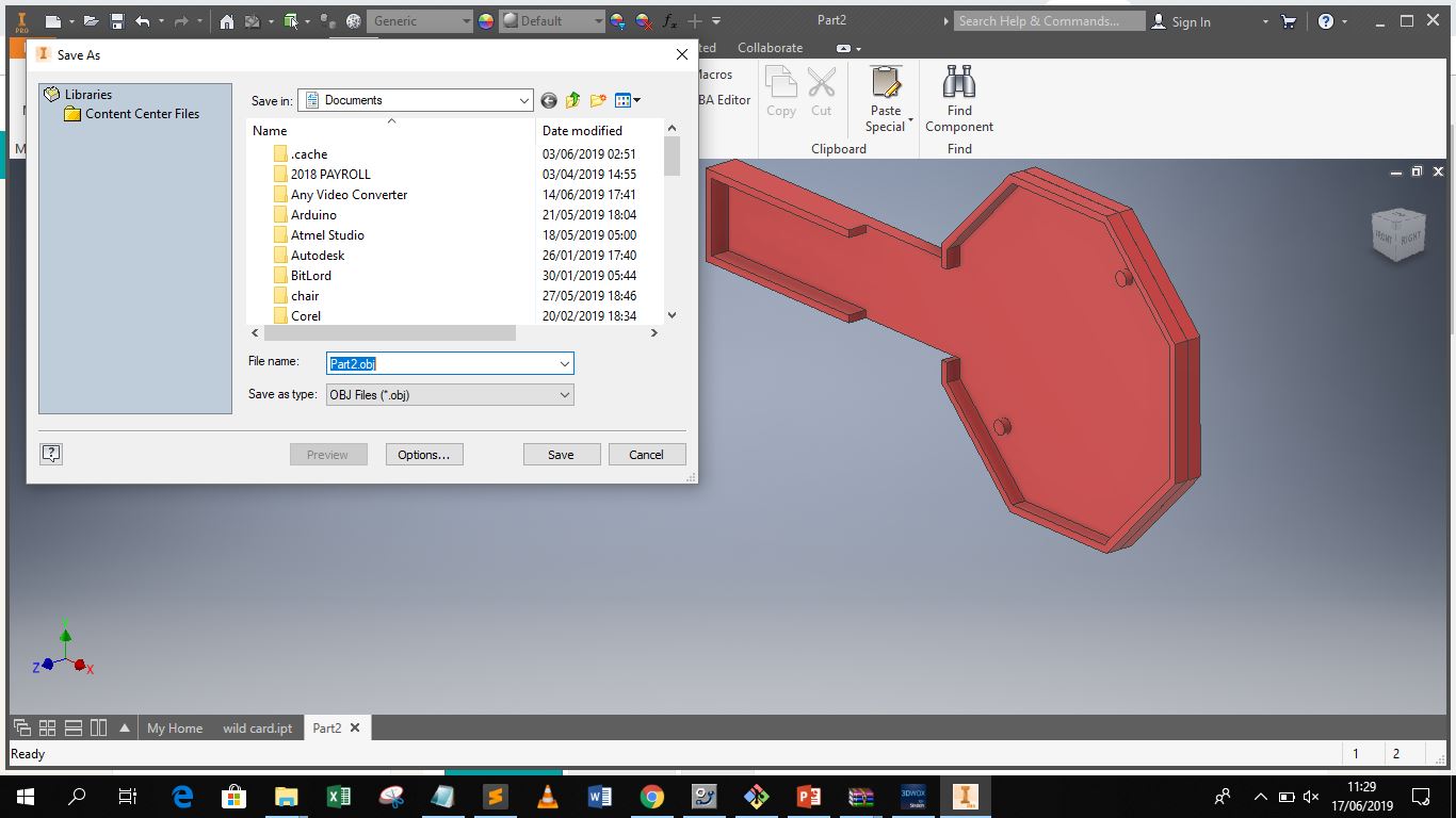
I then exported the design to an obj format which is compatible with the slicer used for the 3D printer available in the lab
I then imported the OBJ file to the Slicer and generated the gcodes necessary
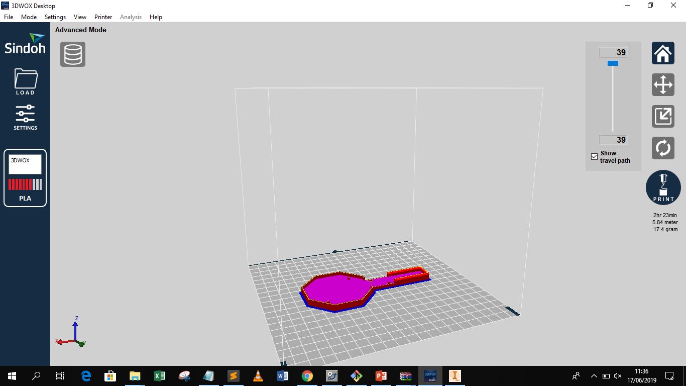
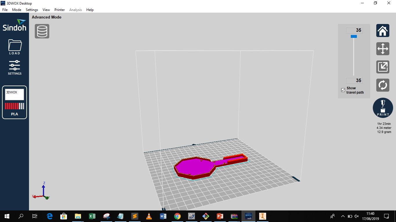
However, I decided to optimize the print and remove unnecessary supports
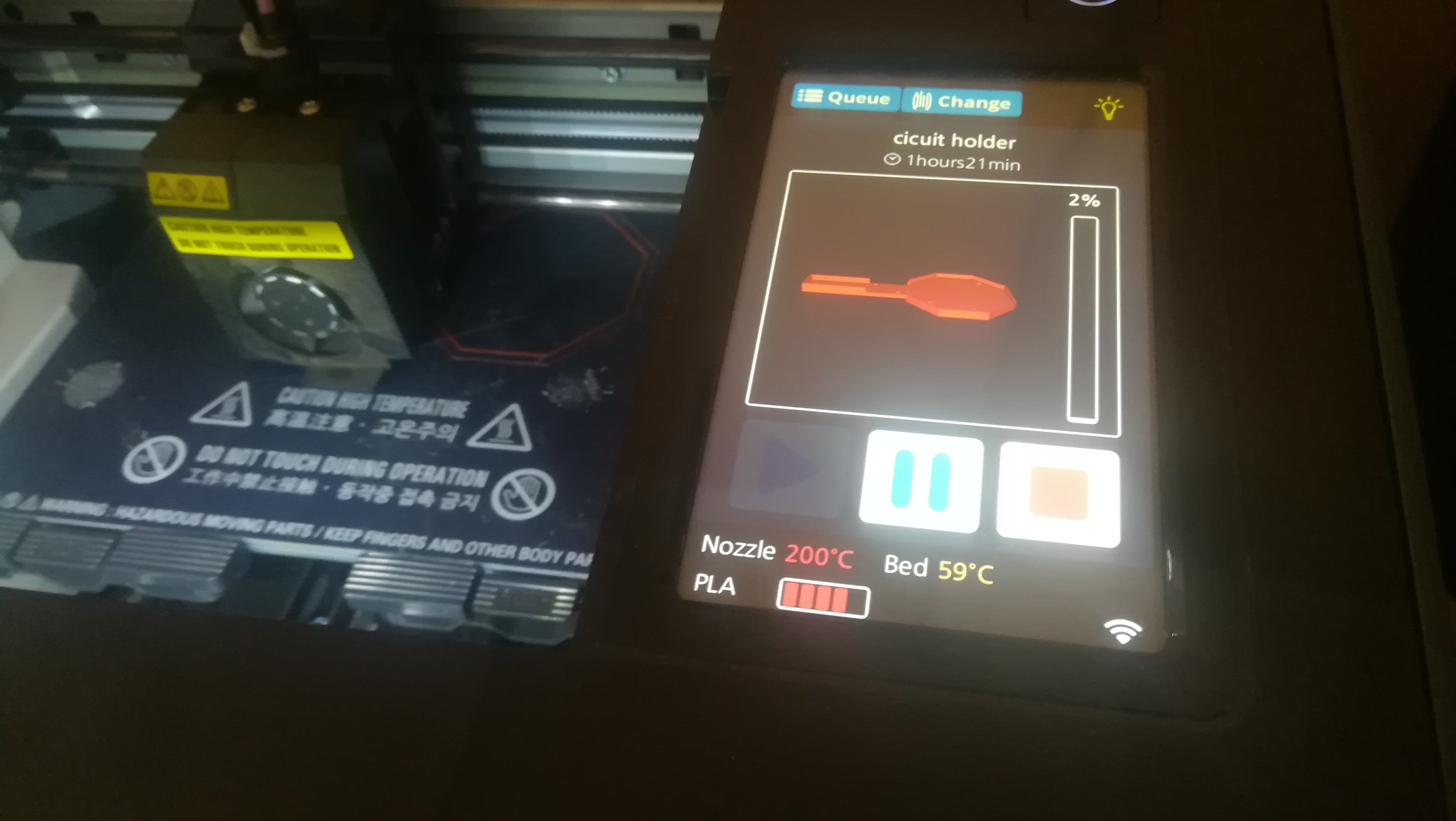
I also utilzed two filaments to produced a different colour effect for the print
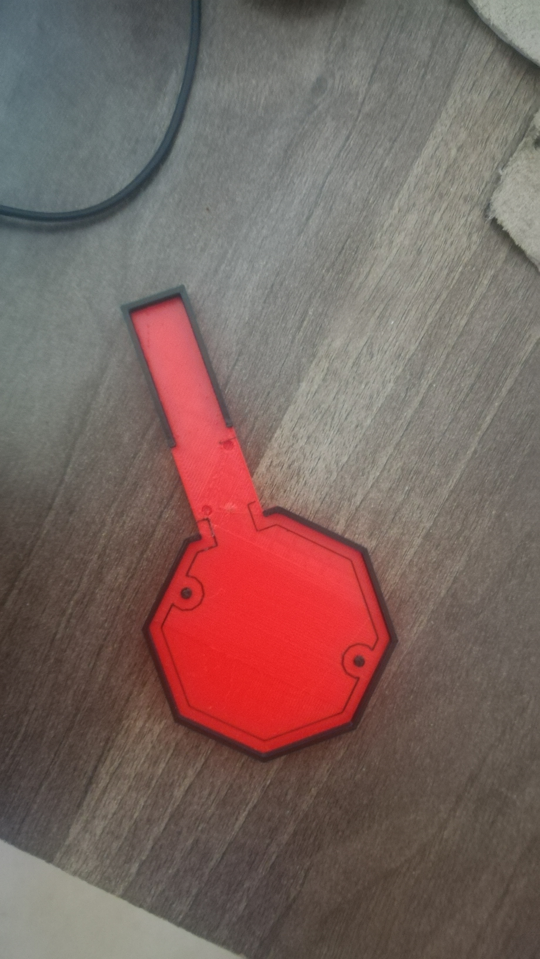
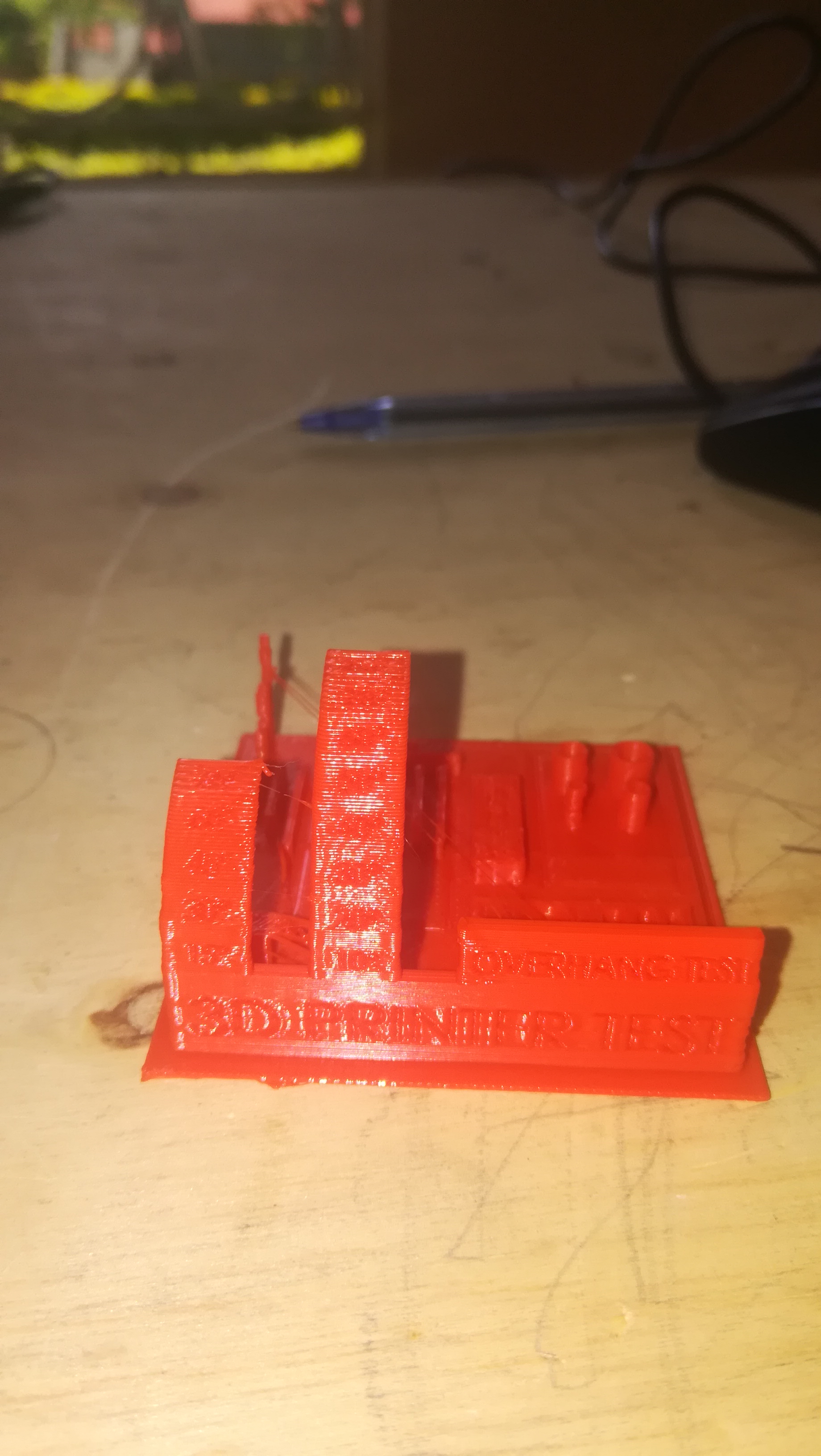
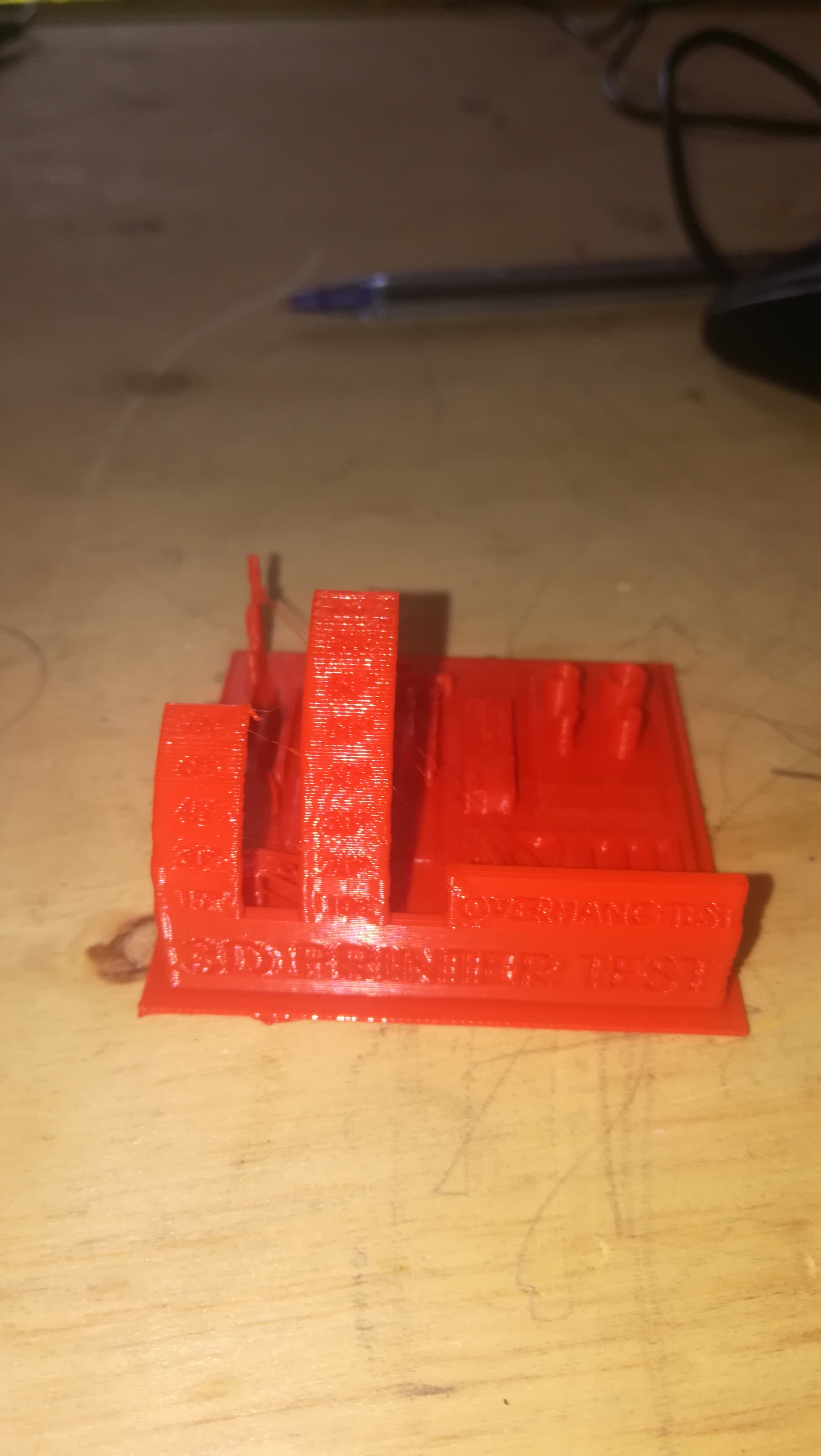
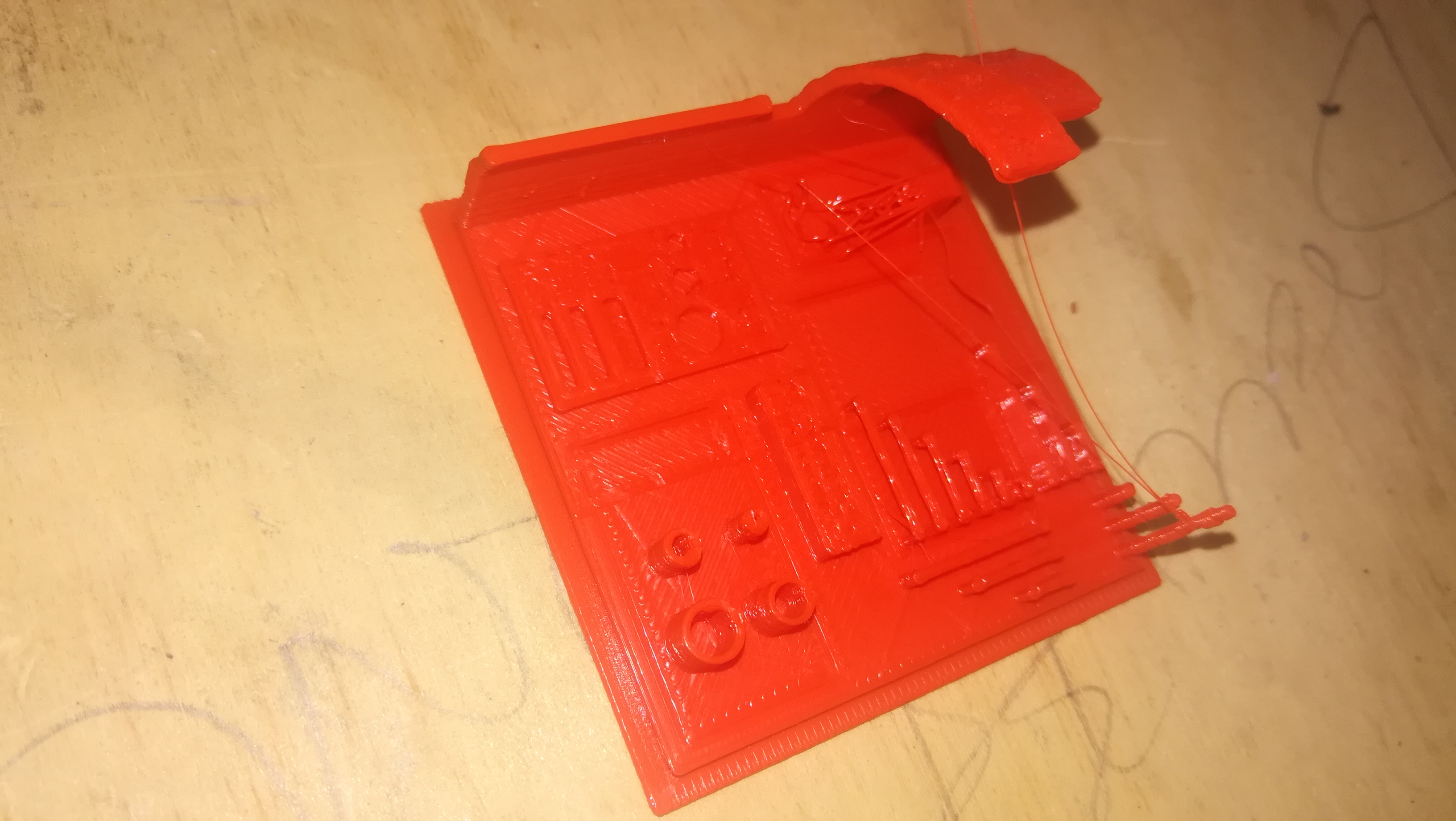
I also conducted tests for the 3D printer. The following are the results, the overhang ing parts were printed accurately with minimal defection. In additon the fine detailed parts of the prints were also achieved with minimal tolerance indicating the printer had very high precision and accuracy.
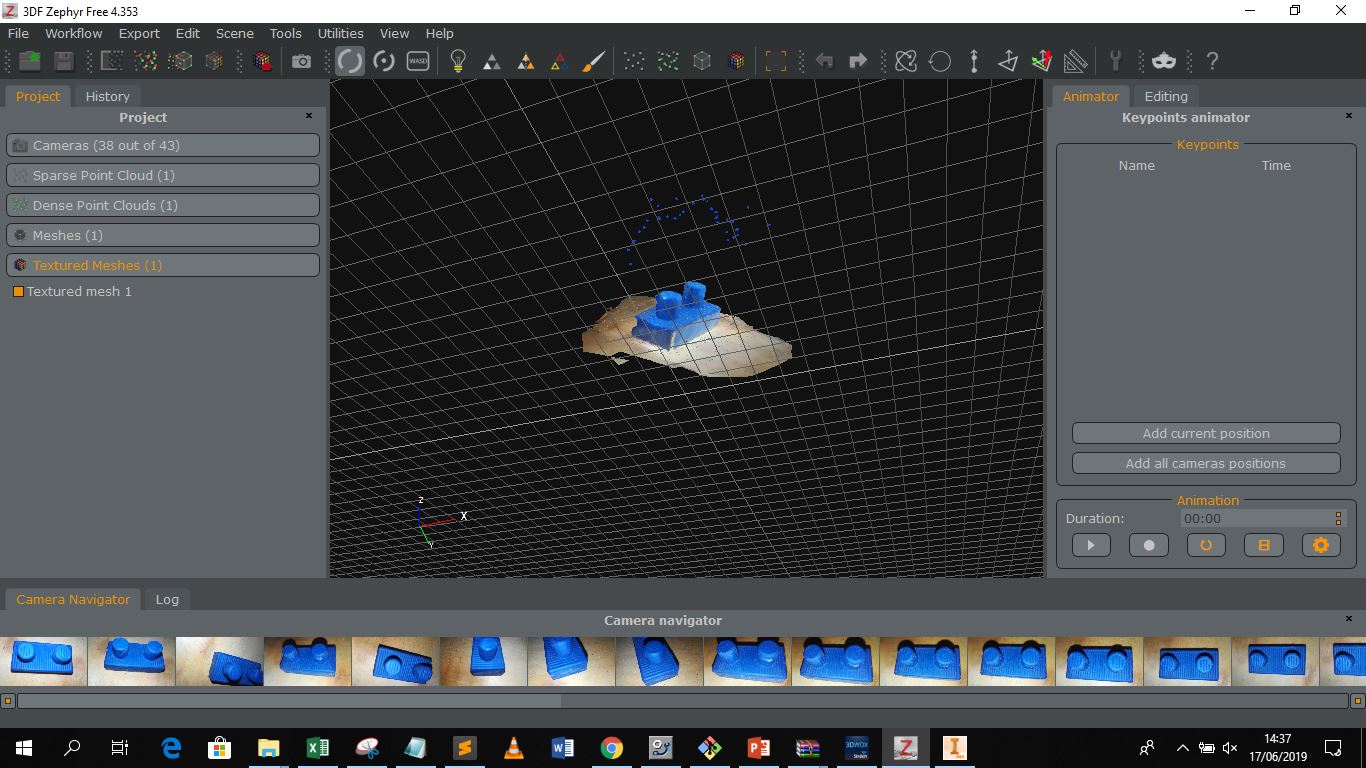
For 3D scanning I utilized the 3D Zephyr software and 3D scanned the first object produced in my moulding and casting experiment. 3D scanning it enabled me to identify the tolerance between the produced object and what was designed using the CAD software, It also provided an obj file that can be used to develop a 3D print of the object
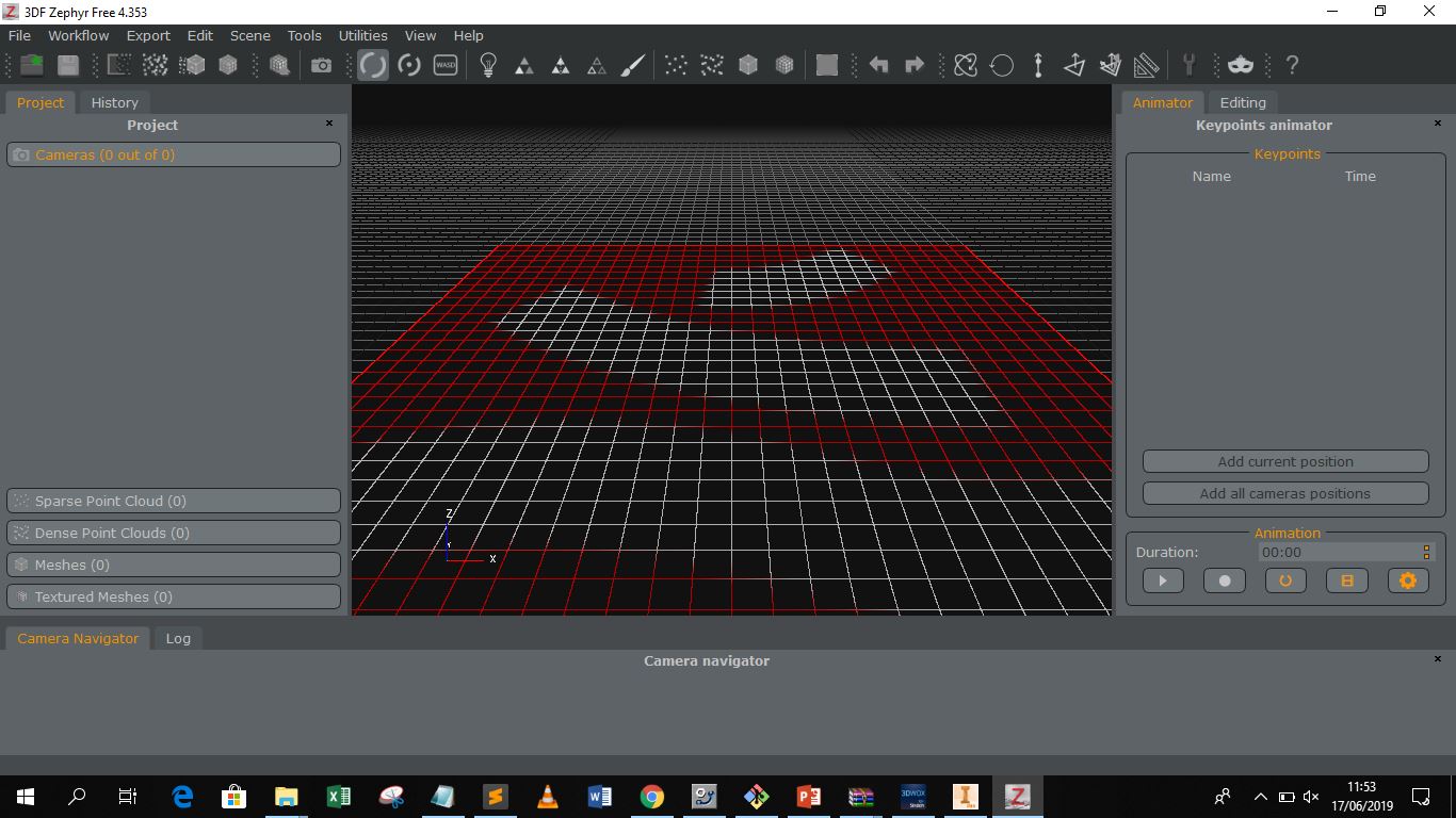
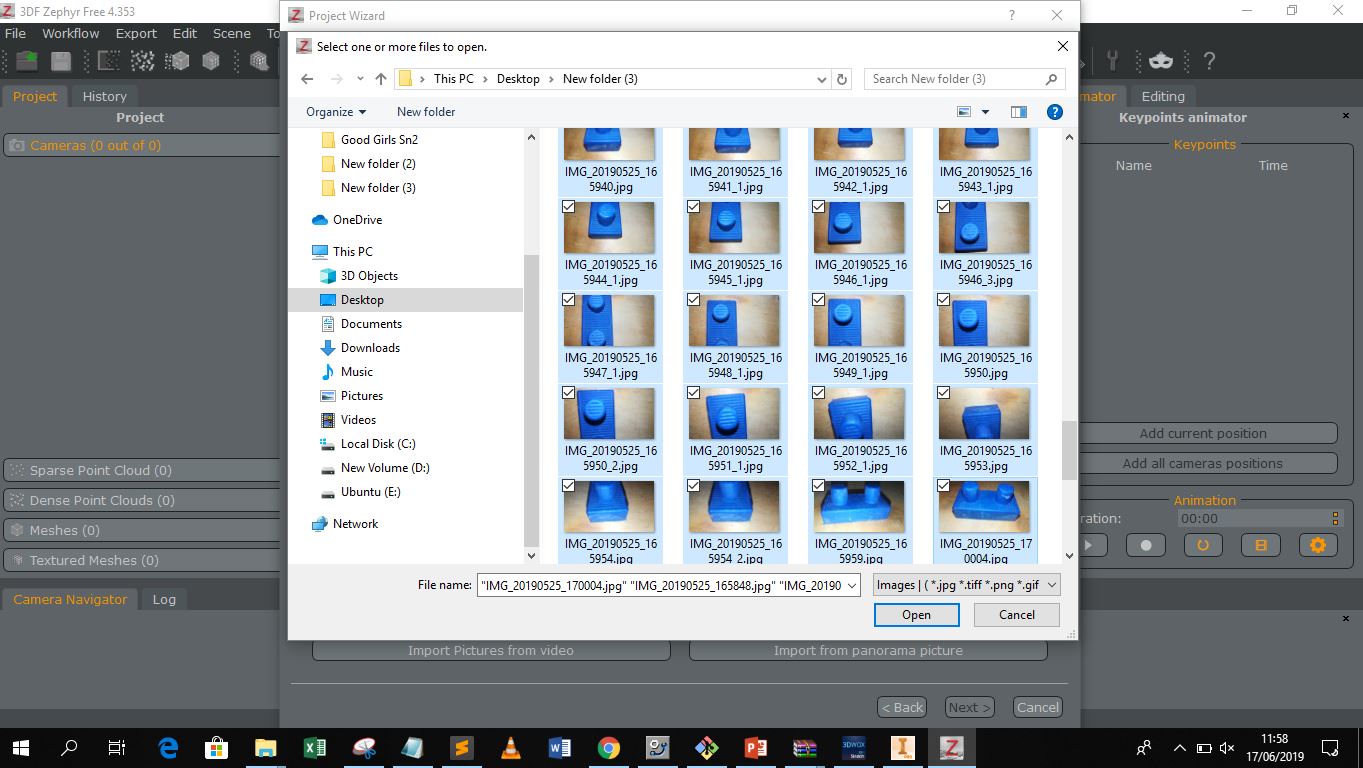
The first step was to take as many pictures as possible at different angles using either a mobile phone camera or a professional camera.
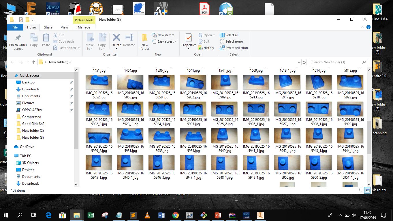
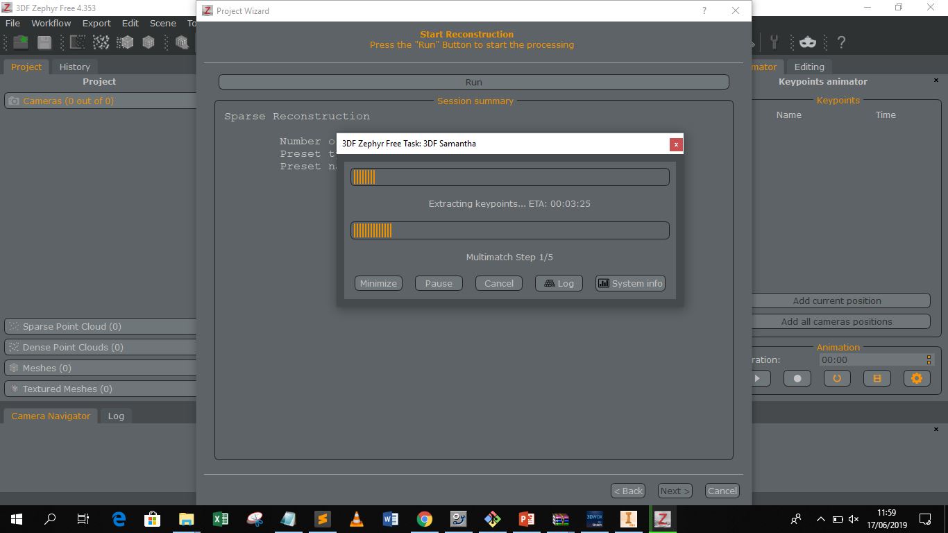
The images are then imported to the software and utilized to generate a textured mesh of varied density of the object. The textured mesh generation has different stages with each improving from the previouse until a dense textured mesh of the object is formed. Then one can export the solid object in the desired CAD format for production.