Introduction
This week we have Two main assignments:
Characterize the design rules for your PCB production process
Make an in-circuit programmer by milling the PCB, program it, then optionally, trying other processes.
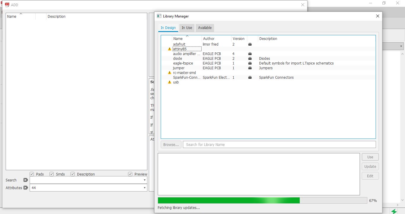
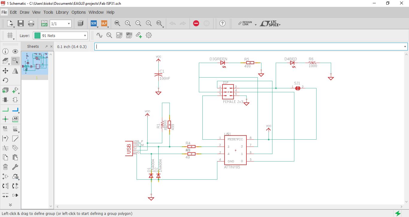
I designed my circuit using eagle the first step was to add parts to my circuit diagram
The next stage was to connect the different parts i selected for my circuit, I used nodes to simplify the circuit diagram, some of the nodes used were VCC and Ground.
The next stage was to design the board, I exported the circuit to the board design and begun arranging the parts as I would like them to appear on the board.
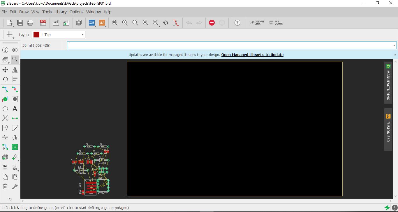
After placing the components the next step was to join the parts using tracts of varied sizes as necisitated by the design. I manual rooted my board, to enhance my freedom in design.
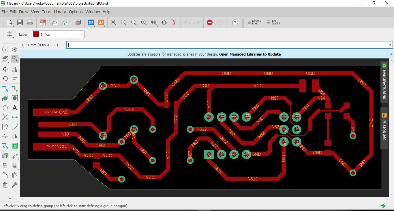
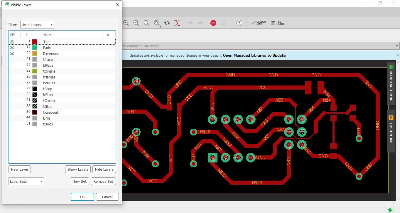
In order to export for machining of the different elements of the board, some layers have to be switched off, for example the process orders involve creating the tracts first, then drilling holes and later cutting out the board
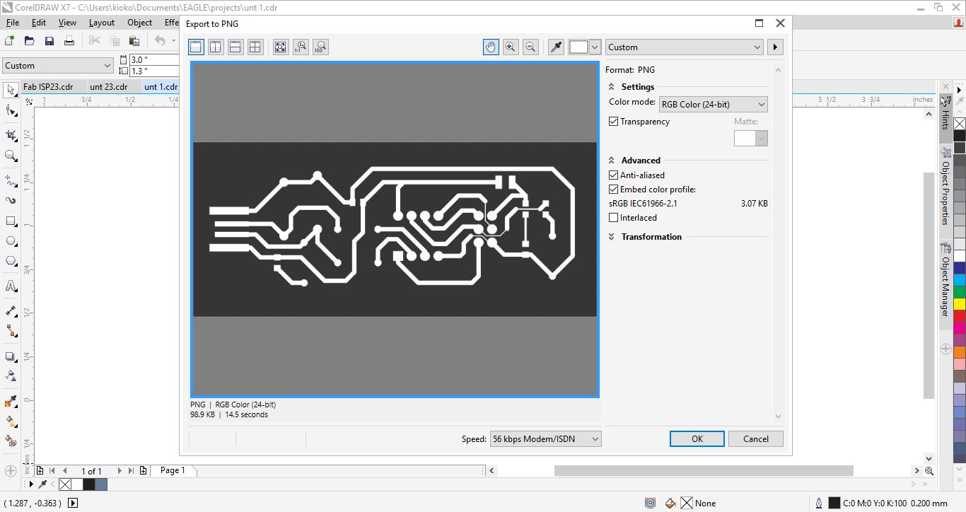
When exporting for png the image did not appear to scale therefore, I opted to expot it as pdf and edit it with Corel Draw.
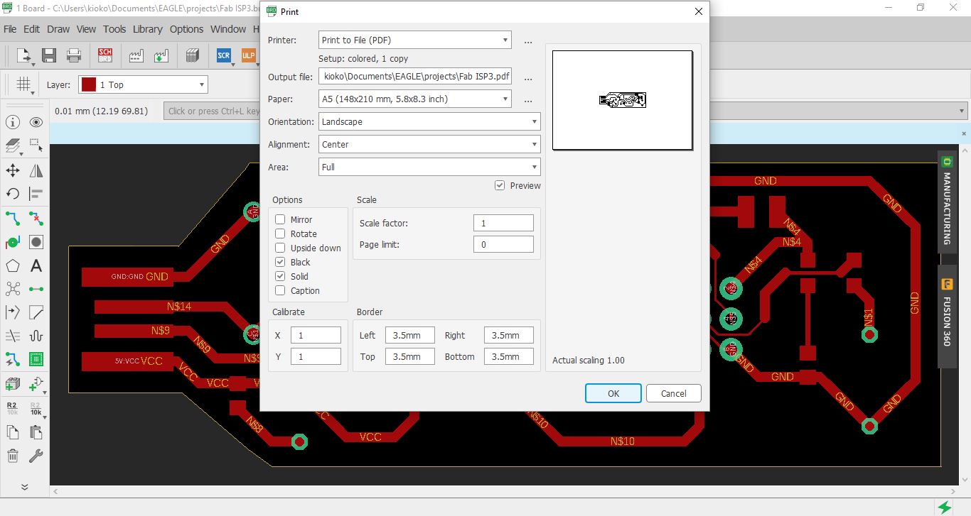
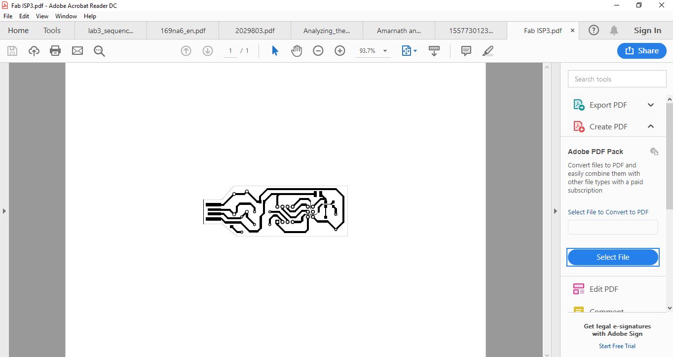
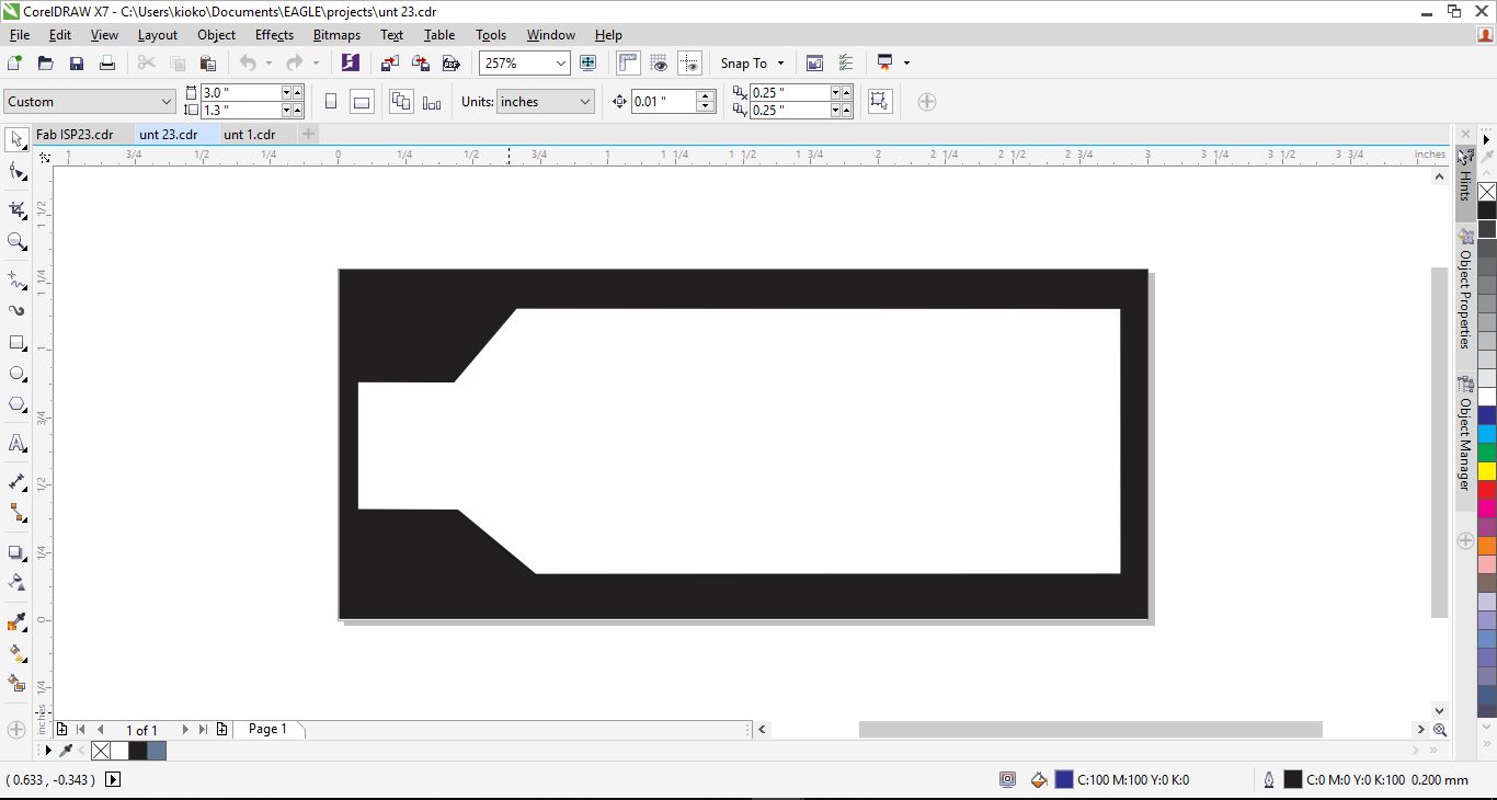
The next stage was to edit out the pdf image to different png files that are relevant for machining. In this case the outline as showed below:
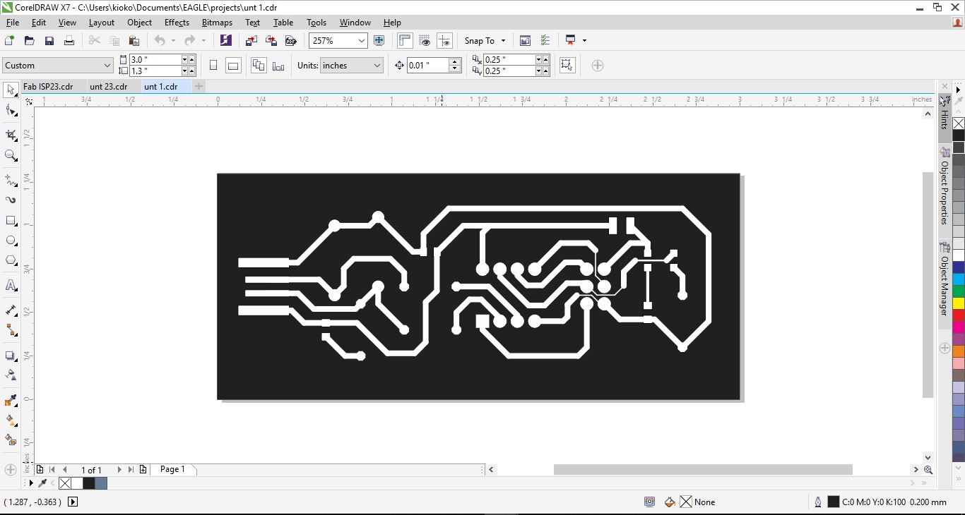
And the tracts as shown:
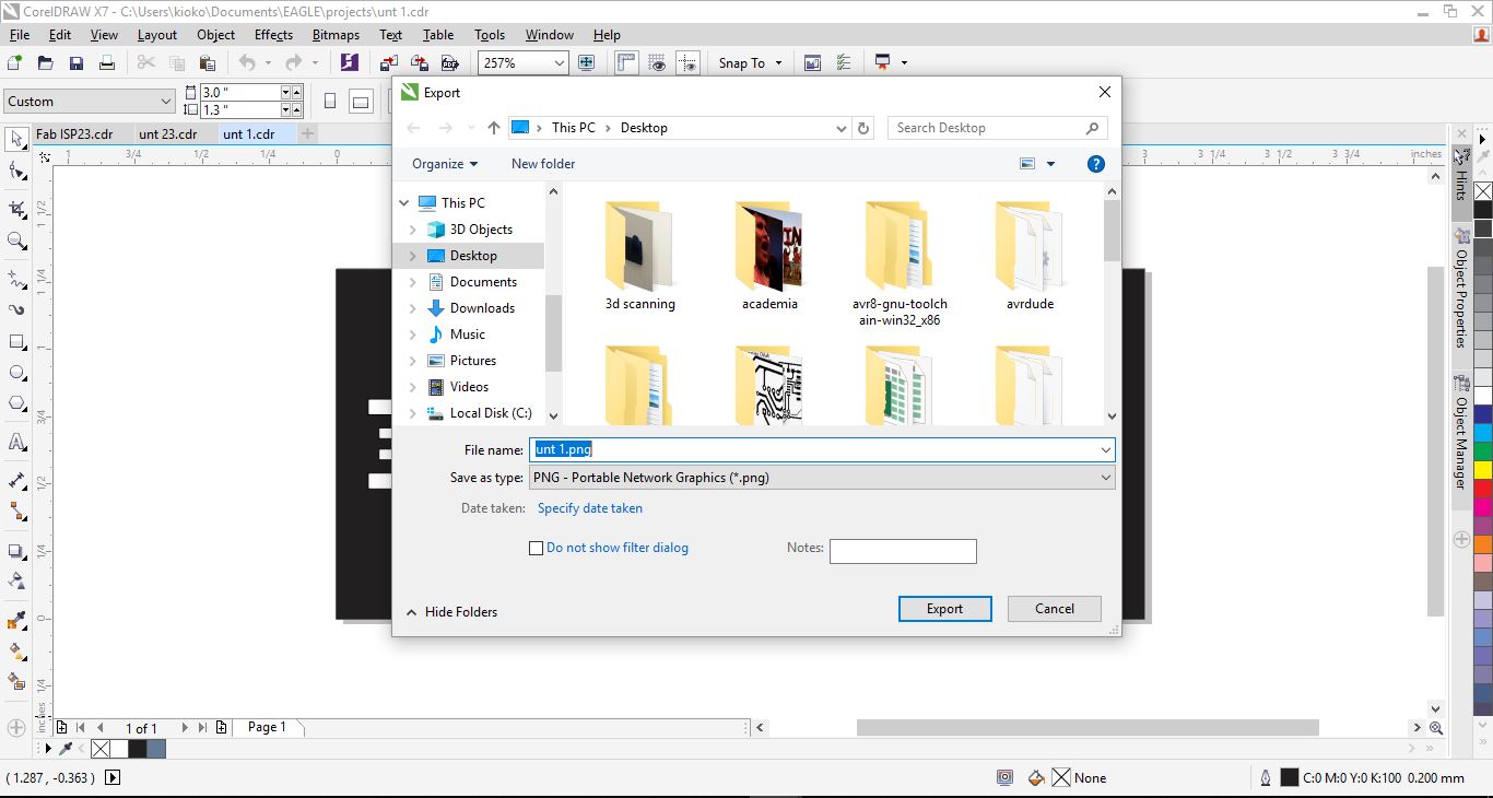
After editing the images out the next step involved exporting the images to png format which is required by the fabmodules processor
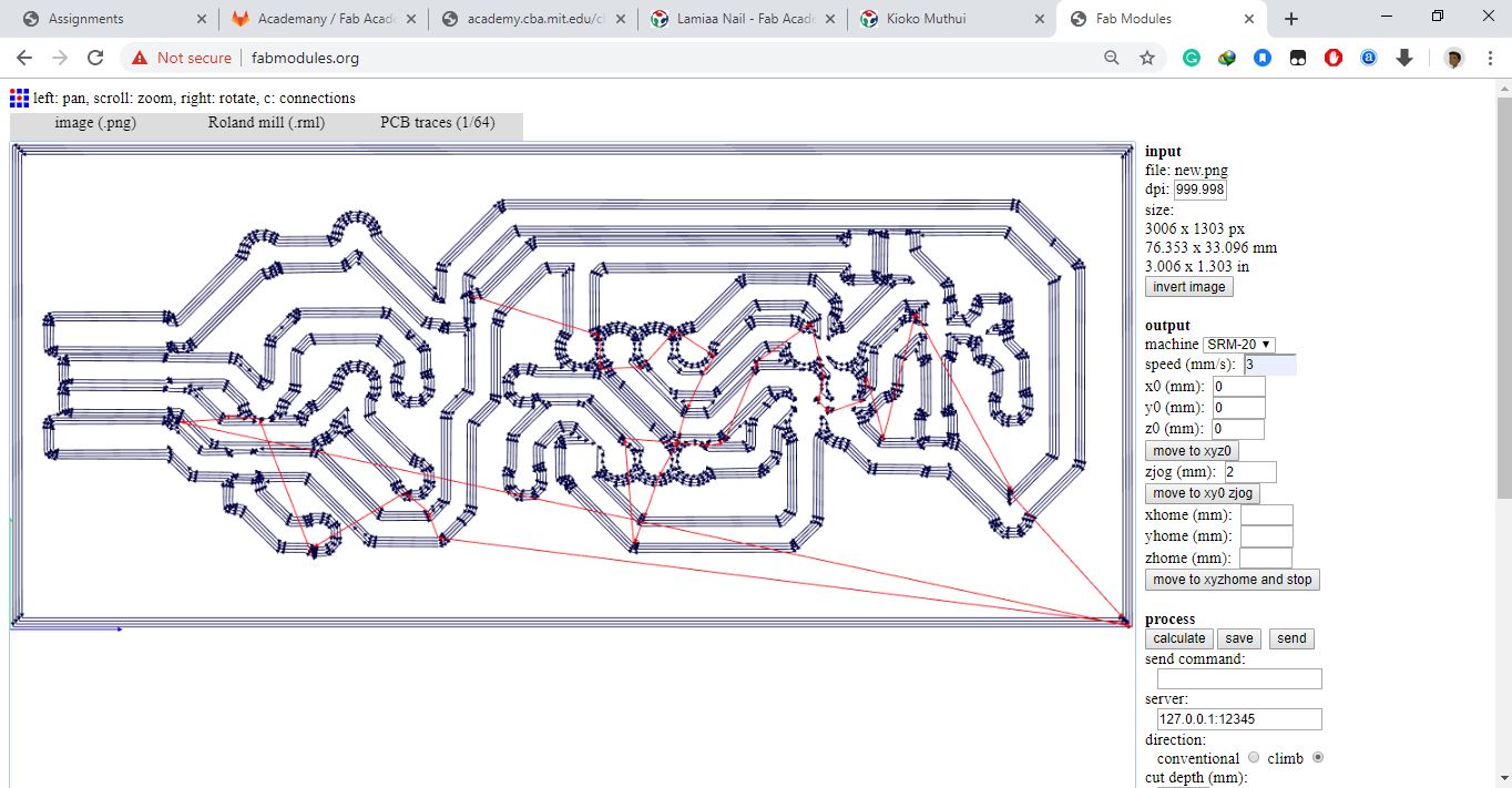
The next step requires one to go FabModules, At fabmodules one selects the file format in this case png then uploads the file and proceeds to setting the parameters for the operation. The parameters include selecting the machine or file format in this case Roland mill. A right tab will then appear where the user specifies the origin of the machine. The speed for the operation and z-jog which is the displacesment of the z axis as it moves across the board. The traces path is shown below using the 1/64" end mill
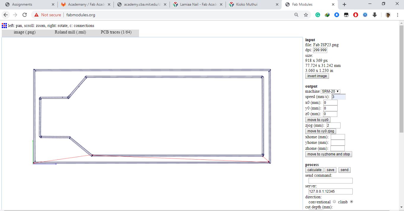
For cutting out the board a 1/32' end mill is used and the other parameters remain the same. After genetrating the tool paths, an option of saving the generated file is provided download the file and input it at the vpanel interface for the srm20 machine.
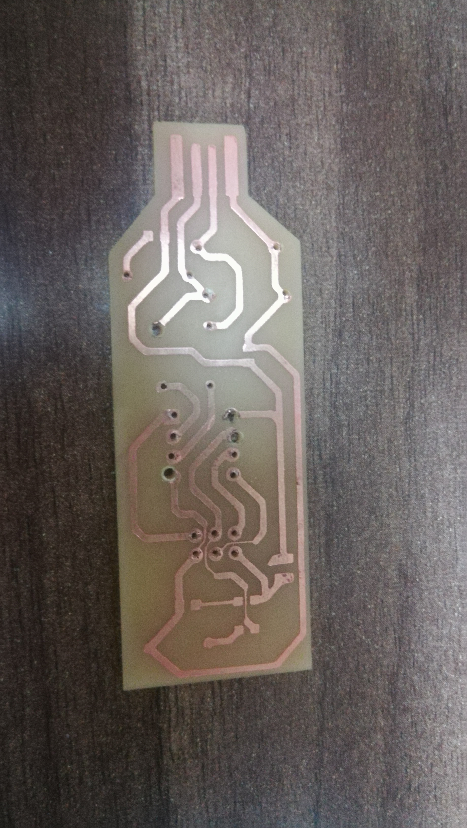
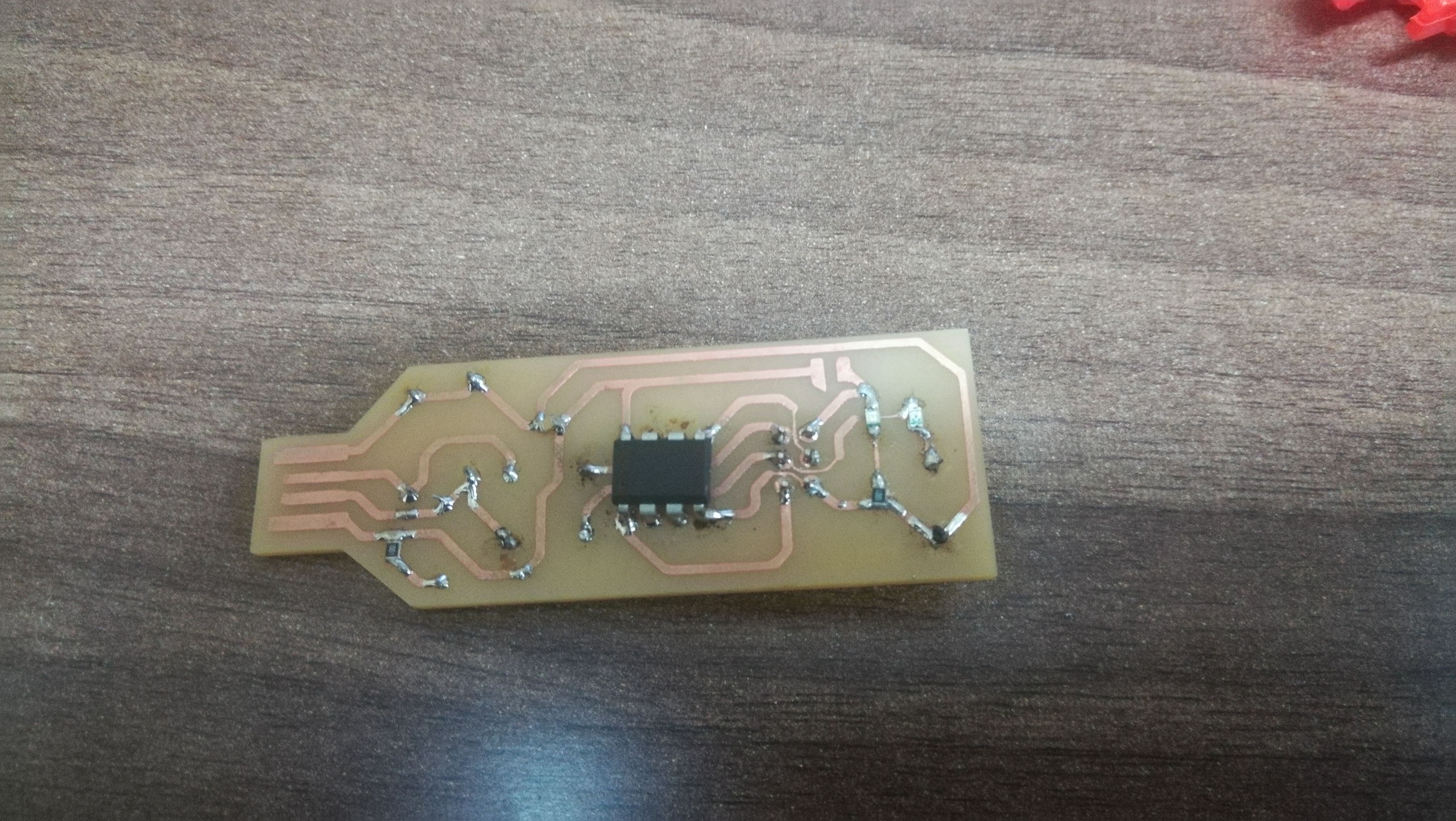
Machine set up is also important. I used double sided tape to place the board and folowed the procedure to set the origin of the z axis. I then uploaded the generated file from fab modules to the vpanel and generated the output. For the board it was important to reduce the speed of the machine and the spindle slightly because the endmill used is delicat. It is also important to monitor the machine as it cuts so as to avoid errors in real time. Also do not change the origin between different operations. The final board is as shown below:
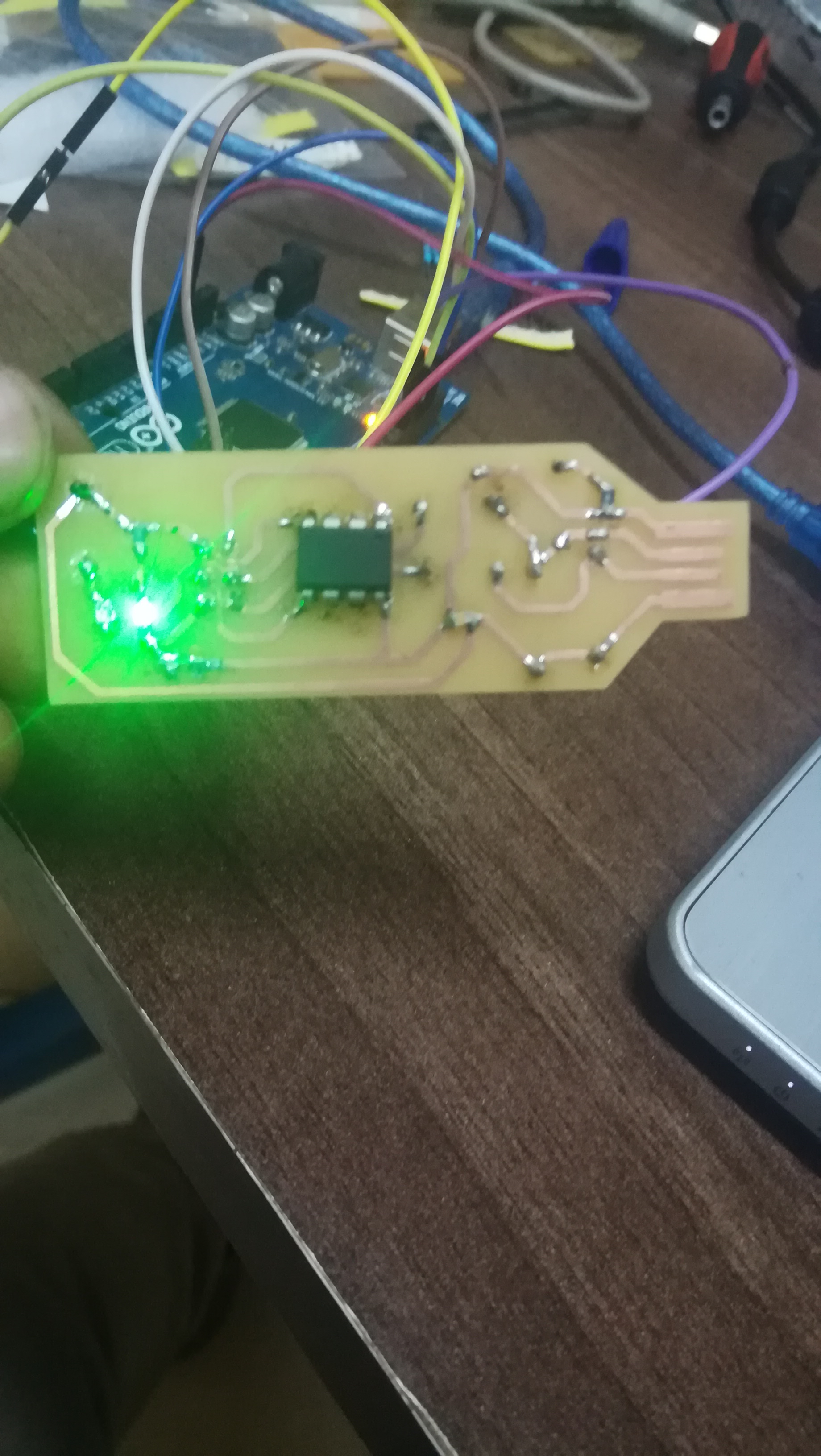
I then soldered my components on the board as shown below:
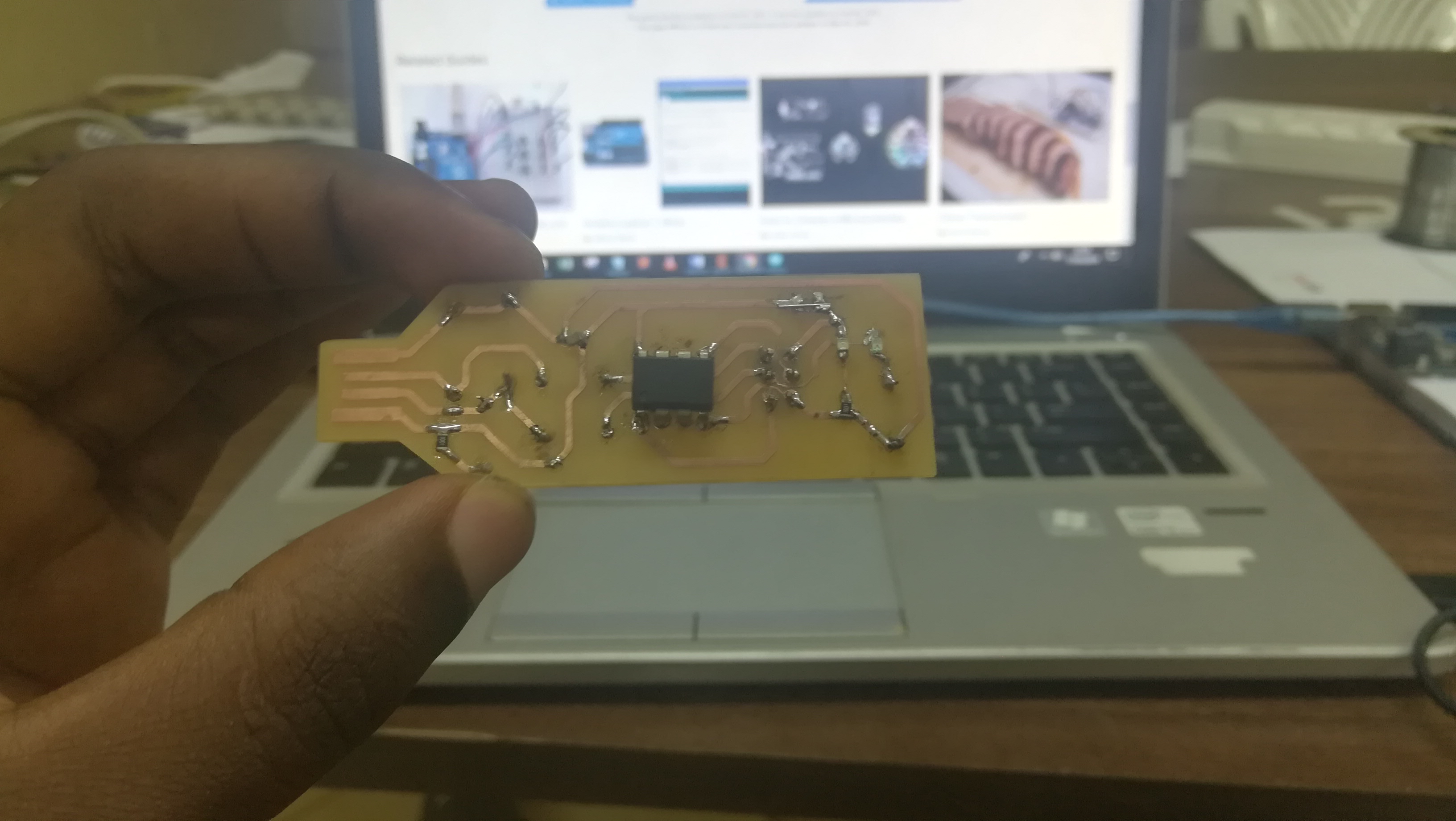
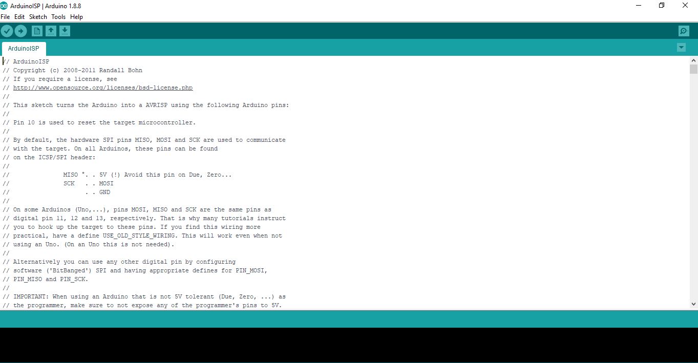
The next stage was to program the board. In this case I used an arduino as my programmer. I uploaded the ArduinoISP program to the arduino mega, and disconnected it from the computer. I then connected my board to the arduino using the provided programming pins. Then connected the arduino back to the computer and set the bootloader to be Arduino as ISP. Selected the board to be Attiny85 and uploaded the blnksketch program
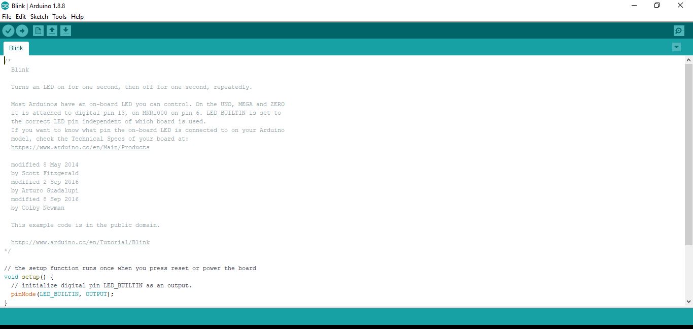
The output is as indicated below the blinking of the green LED
The next step was loading the firmware code to the fabISP, this was quite difficult on the go as I am using windows and i was using arduino for a programmer. The firsts tep involved downloading the firmware from here afterwards unzip the files and save them on your computer Before proceeding ensure you have followed the steps stipulated here After installations are done start git bash and perform the necessary prechecks to check if avrdude and GNU MAKE are set up correctly. Since i am using arduino as my programmer I utilized the data sheet provided to connect the pins as required for this i utilized the data sheet as provided
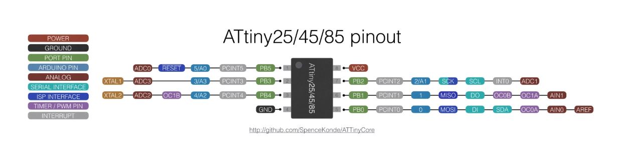
The pins were connected as follows:
5v---5v
GND---GND
RESET---PIN10
MOSI---PIN11
MISO---PIN12
SCK---PIN13
Additonal information on setting up the arduino as a programmer can be found here
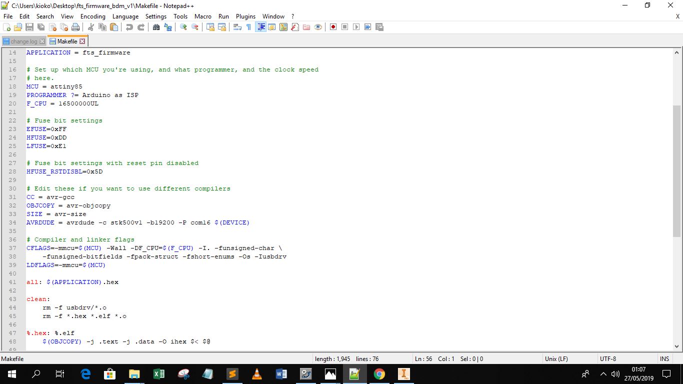
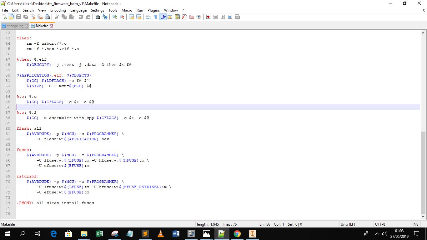
The next process involved altering the make file in the unzipped firmware folder, from the tutorial it was necessary to do that using the notepad++ editor. Since i am using the arduino as a programmer and attiny 85 I edited it as shown below
The next step was to navigate to the firmware folder using git bash, however before this the arduino has to be set up prior using the steps indicated before. After navigating to the folder run the make clean command.
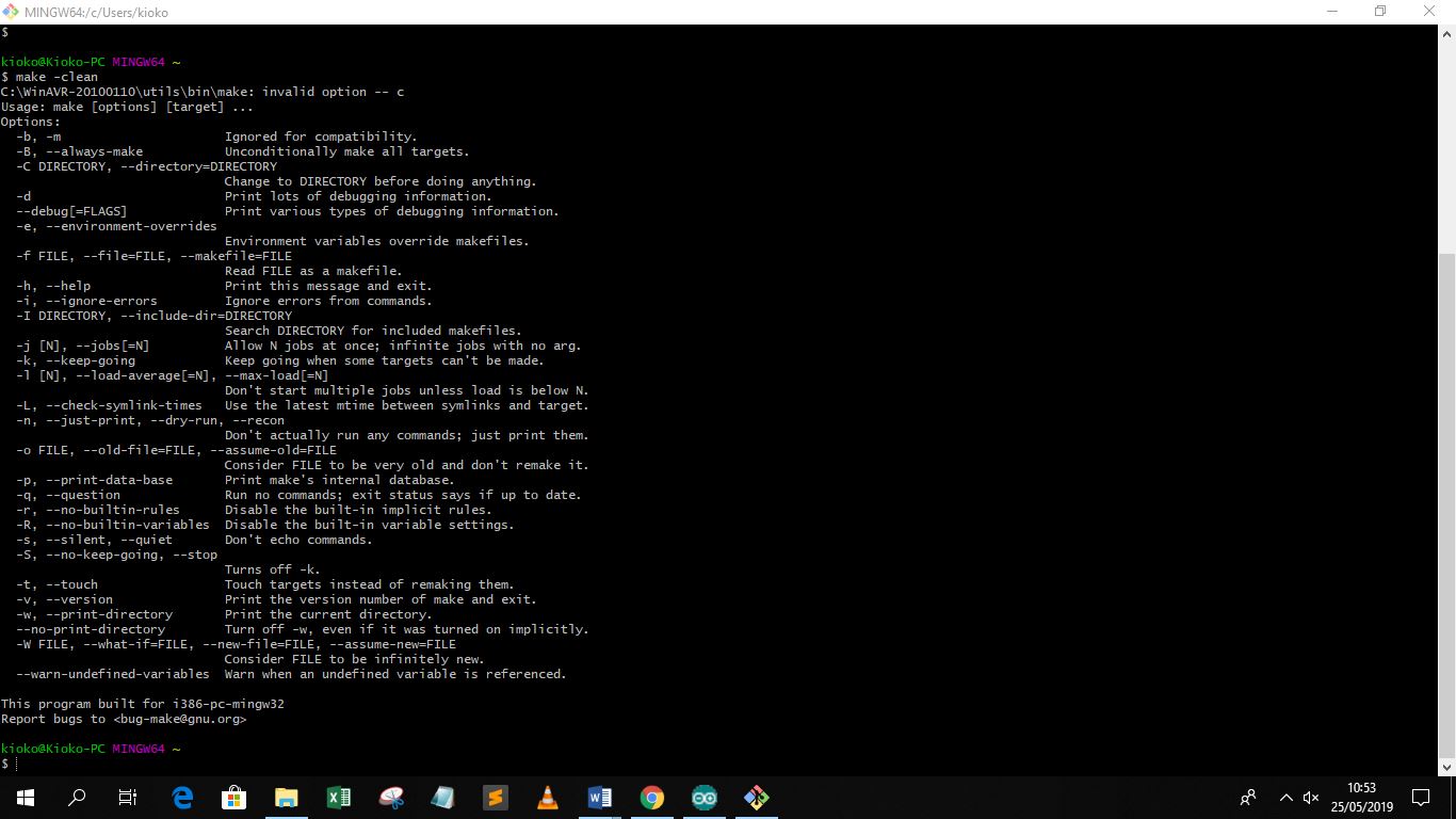
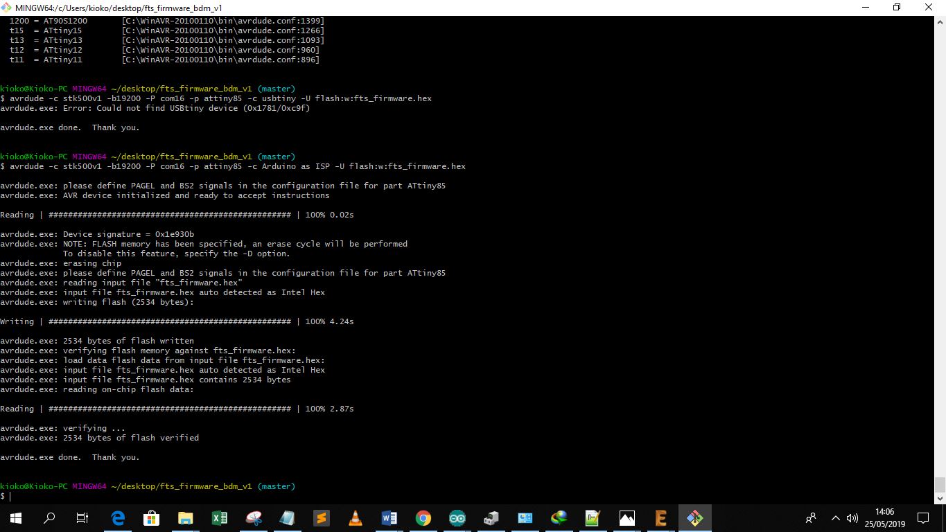
After running the command proceed to make flash, at this point i found several errors based on unidetifed usb command the program indicated not found, i then discovered this was because my programmer was not directly mounted to the PC but through the Arduino. I therefore edited this part out as shown below:
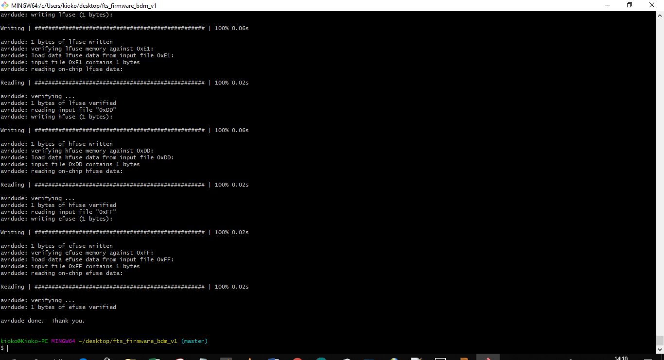
After editing I run the make flash command and it was a success as shown below