Introduction
This week we have Two main assignments:
Assignment of this week is to model (raster, vector, 2D, 3D, render, animate, simulate, a possible final project, and post it on my class page
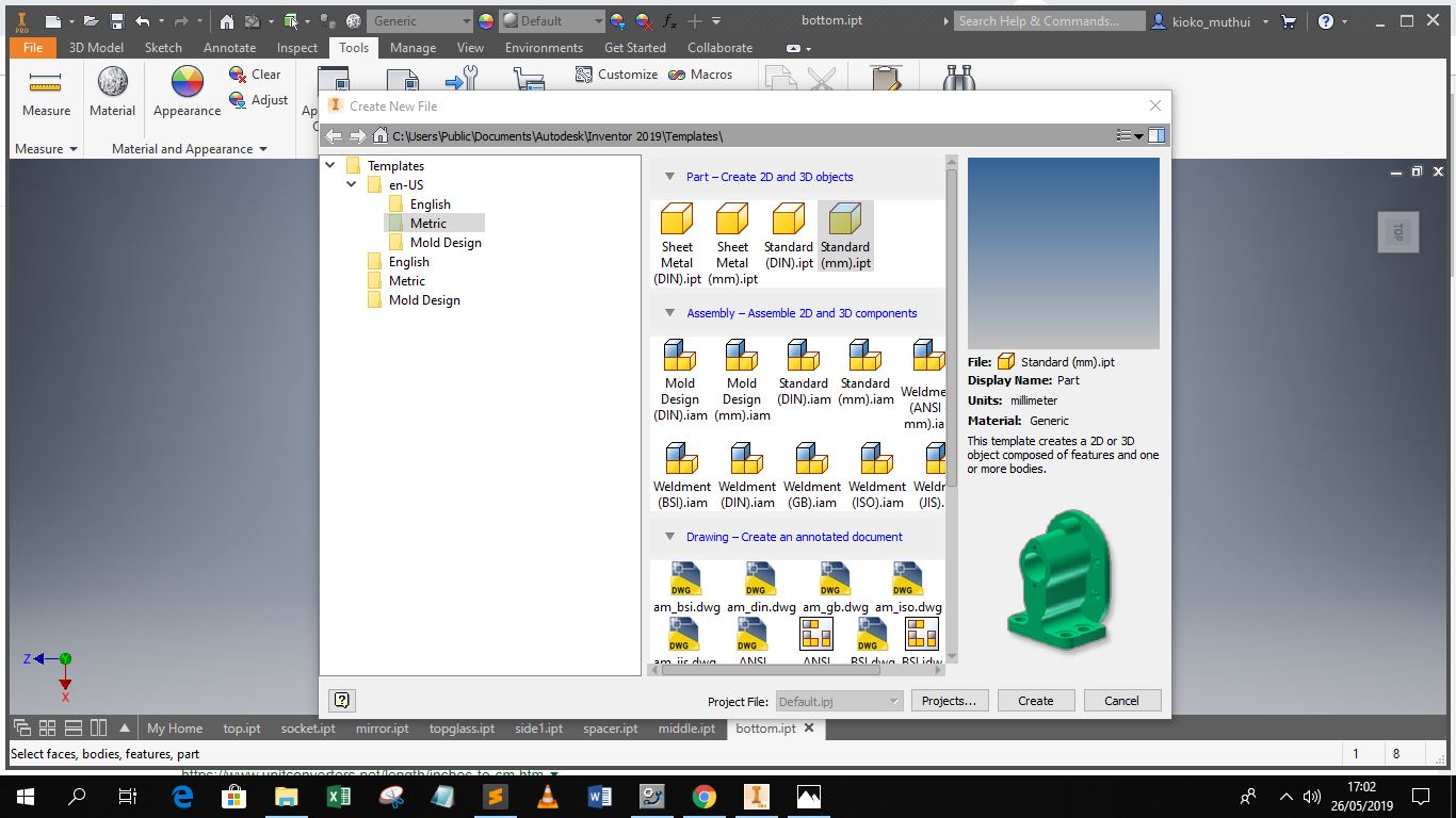
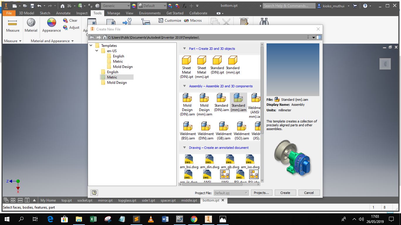
For this assignment I used inventor to create the design of my final project. For the design i created different parts of the table and assembled them in the last part. When creating a file in inventor one has to specify he type of drawing to be done and the units to be used. In my case i am creating standard parts but later on I will create an assembly file. The units can be selected on the left window panel whether its a metric or english unit. In my case i will use milimetres.
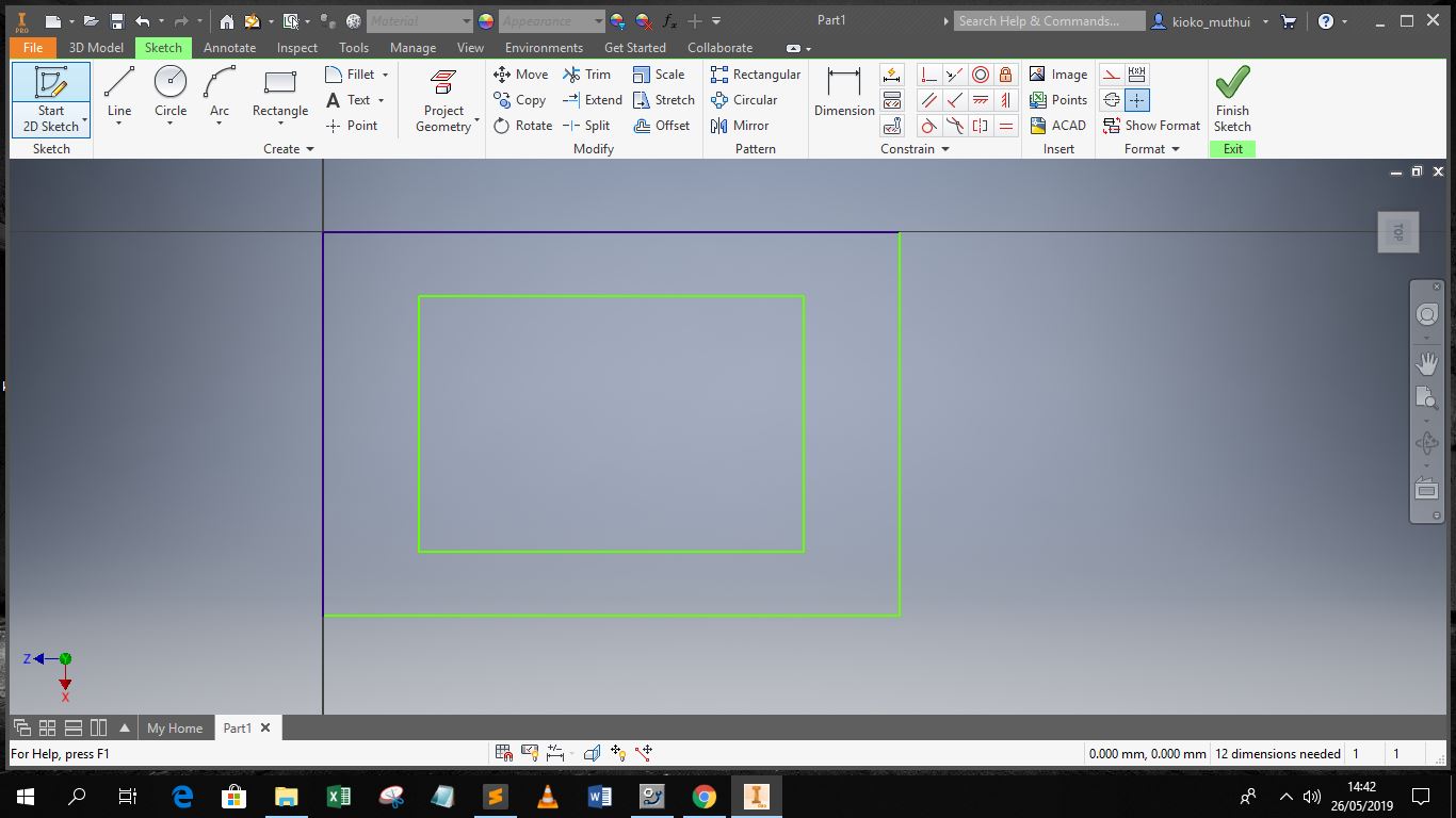
The first stage of any 3D drawing in inventor begins by sketching a 2D drawing, in addition one has to choose the plane of the object they are drawing, nevertheless this can be changed after already drawing, it is however importnat to ease assembly of objects as the orientation will be in one direction.
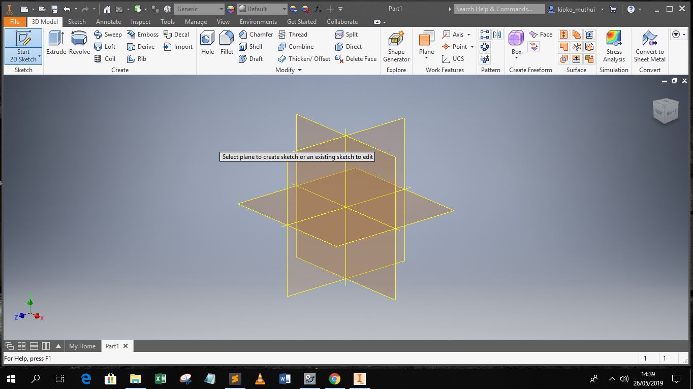
When drawing in the 2D sketch mode one can utilize a variety of tools and command to produce the final object
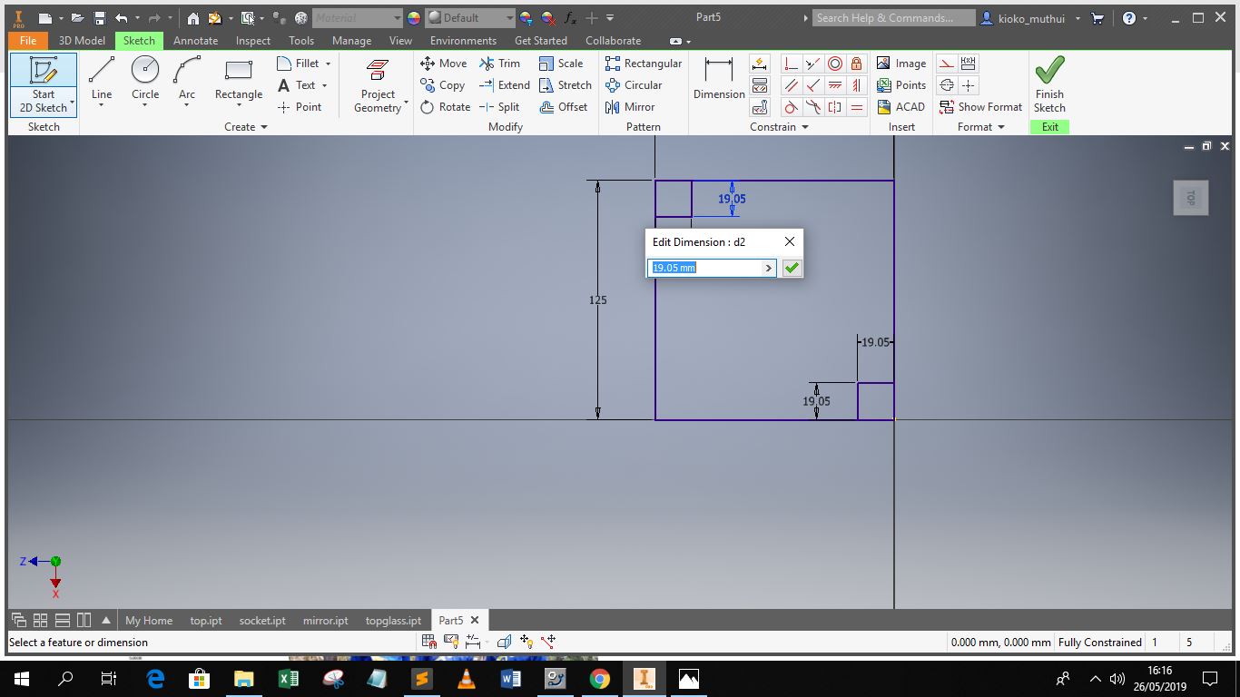
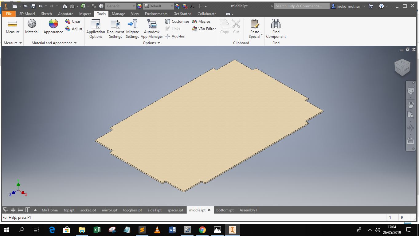
After drawing in 2d one completes the skethc then goees ahead to perform modifications as necessary in this case extrusion to the required object thickness
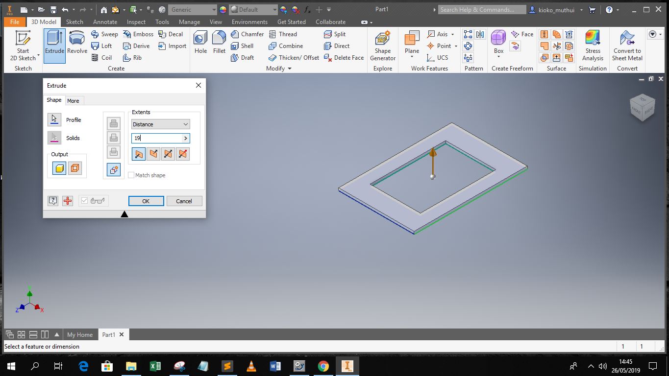
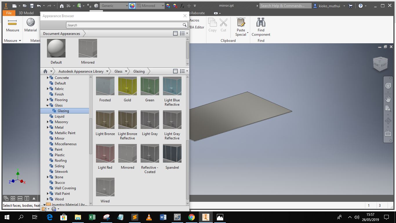
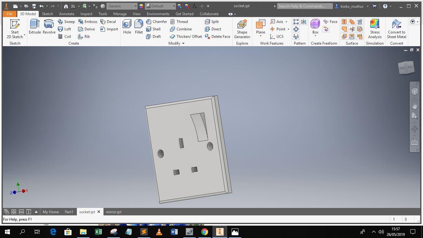
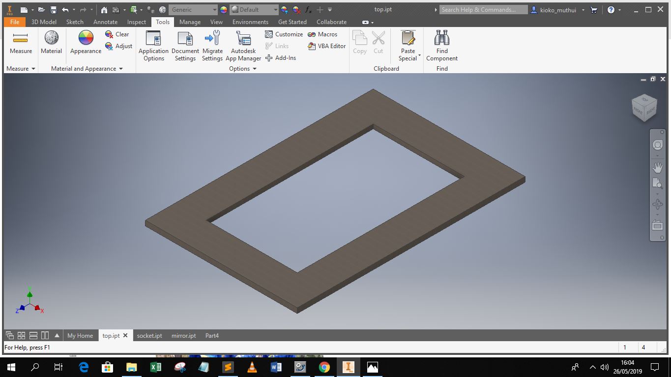
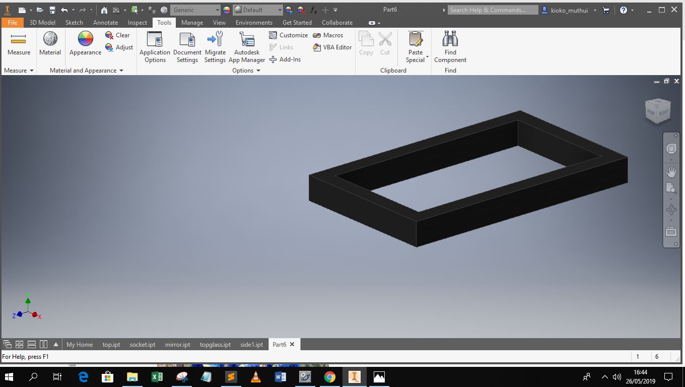
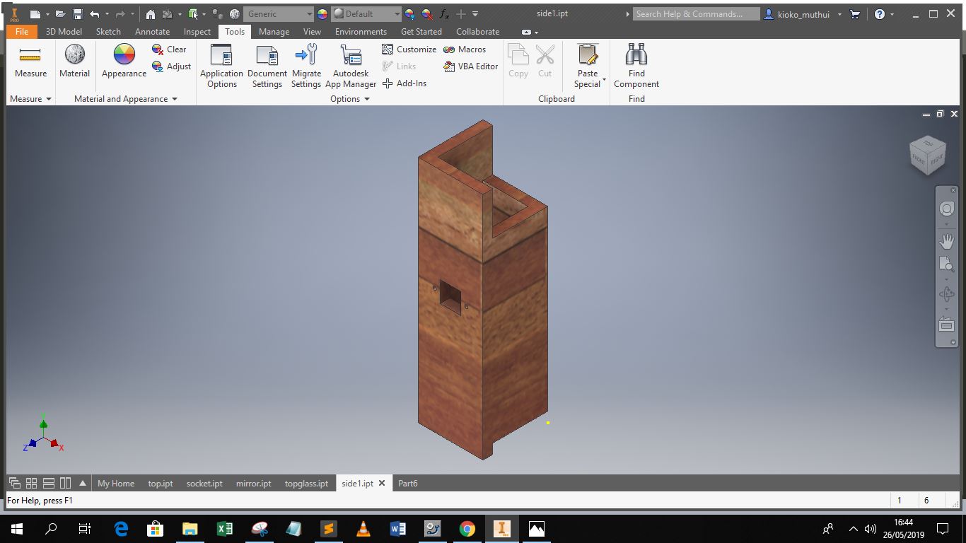
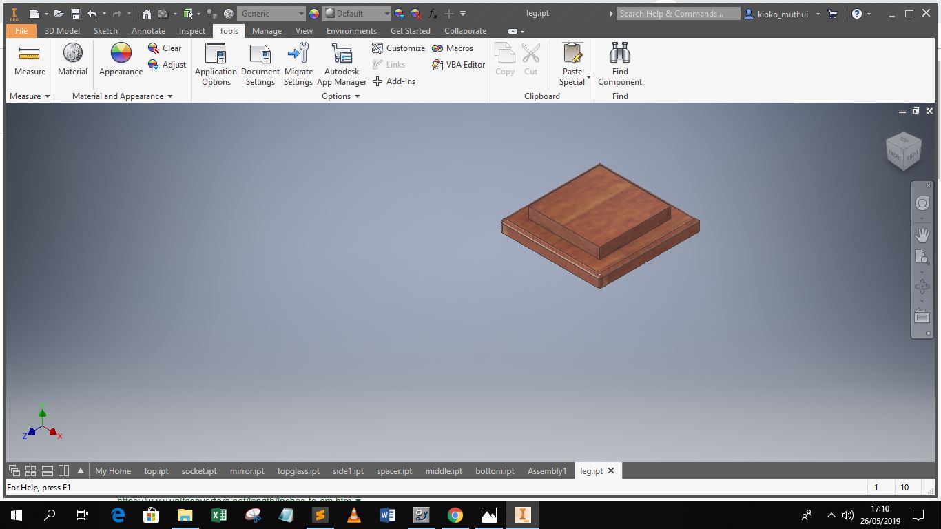
After creating the 3D object, I went ahead to select its physical properties which include its appearance for visualization and the object physical parameters, this is important especially when performing engineering simulation on parts, before final production to minimize errors. Below are some of the parts I designed
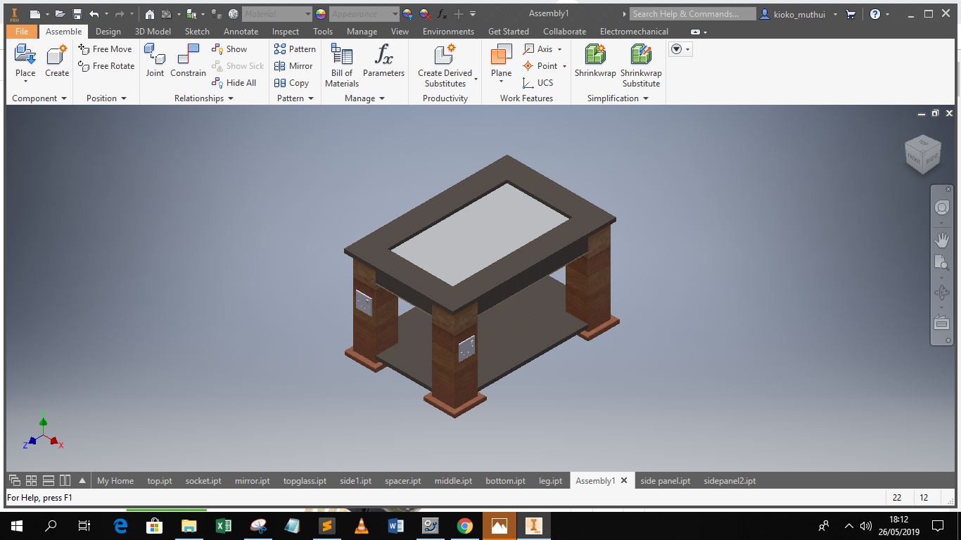
After completing the designs for parts, I went ahead to assemble the final design, the first step was to create the assembly file.
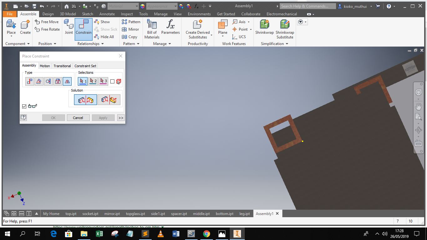
In assembly one imports the object files one by one as they are placed on the workplane, before placement one can edit their orientation to minimize complexities in assembly.
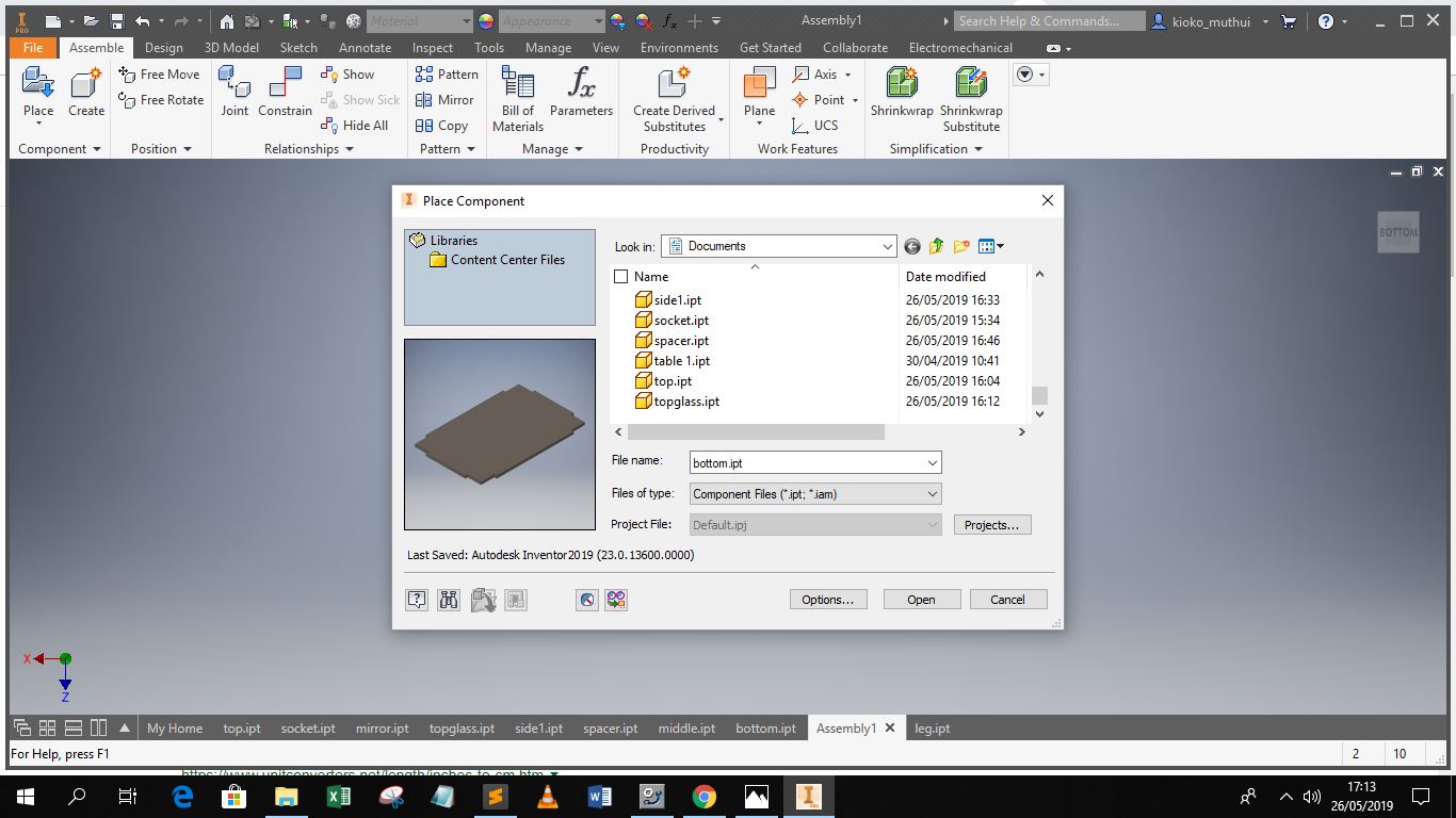
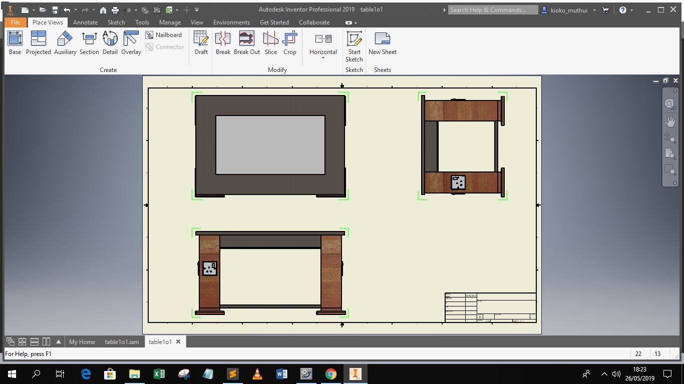
After placing an object one has to set constraints so that the entire assembly can be structured in a wholesome manner. Constraints also minimize errors in placement, as ones level of interaction with the screen is not from a 3D perspective. Therefore how an object appears in the Front view is not the same from the Side View.
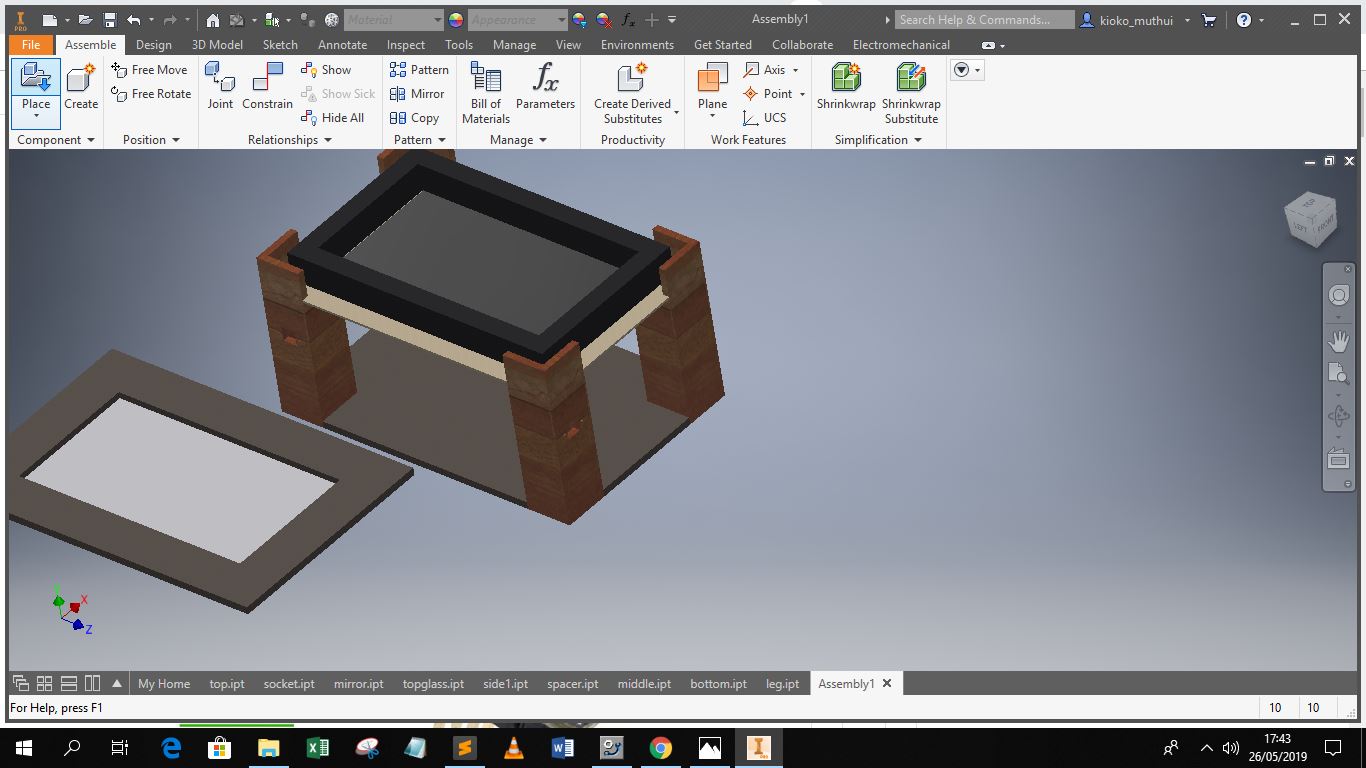
This is the final assembled design