Introduction
This weeks assignment is:
Individual assignment: “Add an output device to a microcontroller board you’ve designed and program it to do something”
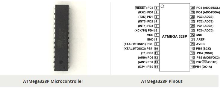
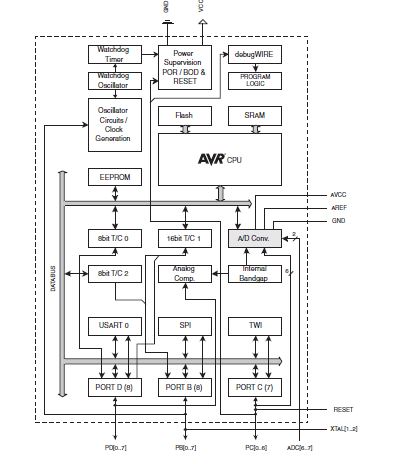
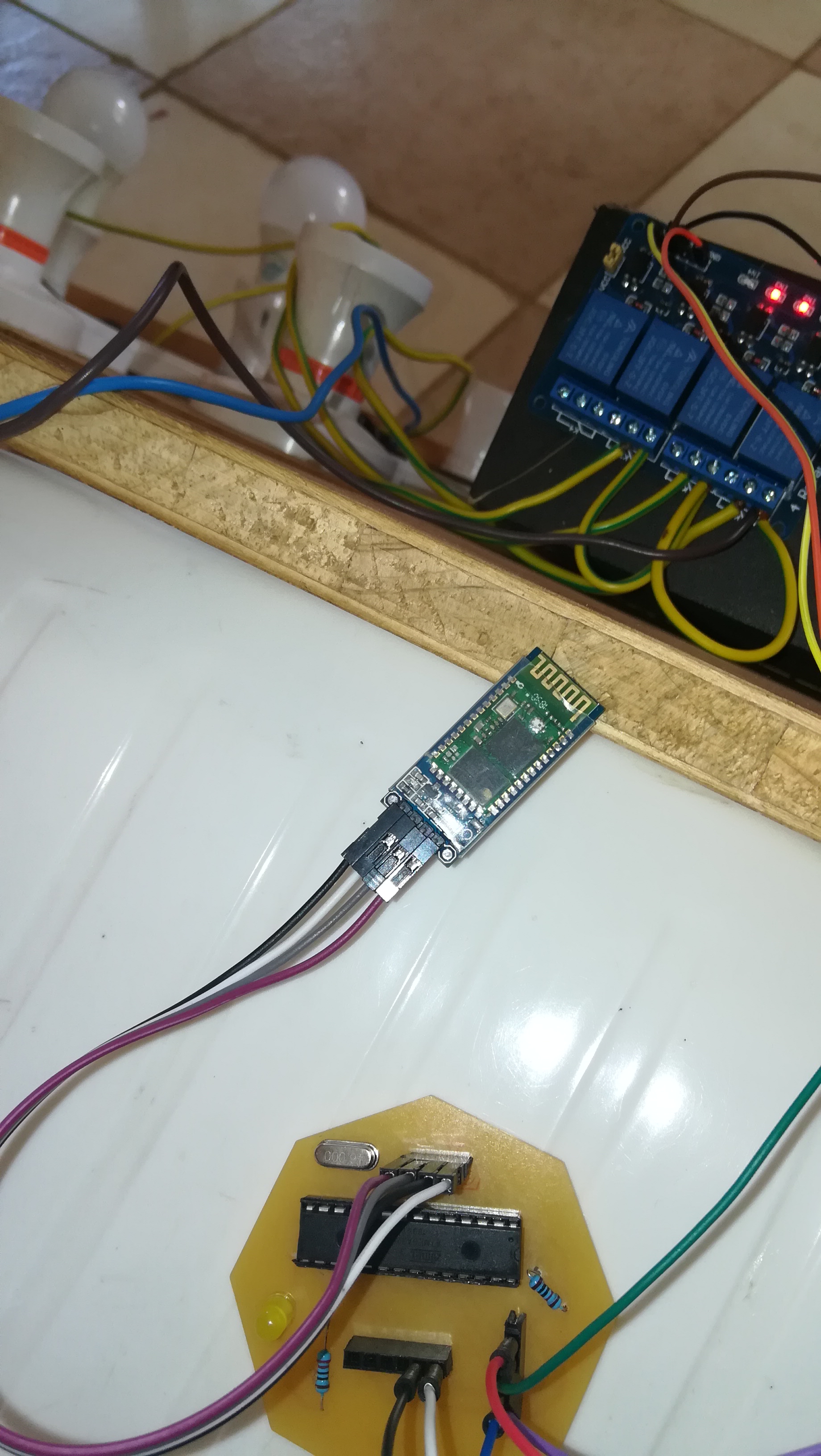
For this project I used my board to control a relay module and later on expanded the design for the network and communication assignment using a bluetooth module. I used the Atmega 328p for this project
The block diagram of the microcontroller is as shown below:
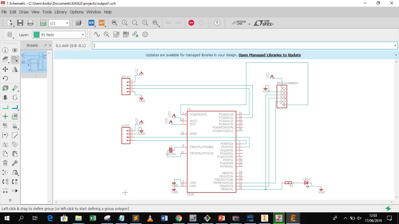
I then utilized Autodesk Eagle to create the schematic for my board design. Instead of placing the actual boards on my board design that is the HC-06 and the relay module i used header pins matching the pin layout for the modules thus the board can easily be interfaced to the specific modules this is shown below
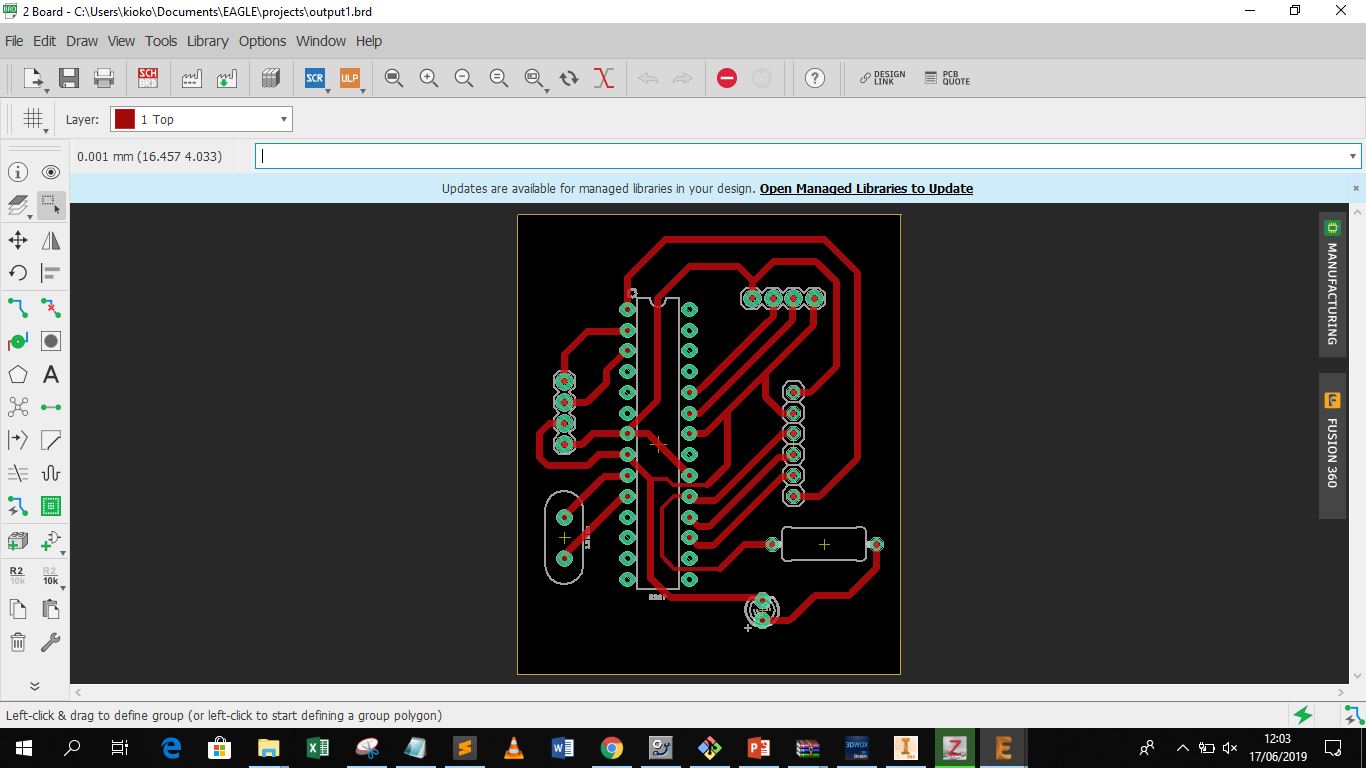
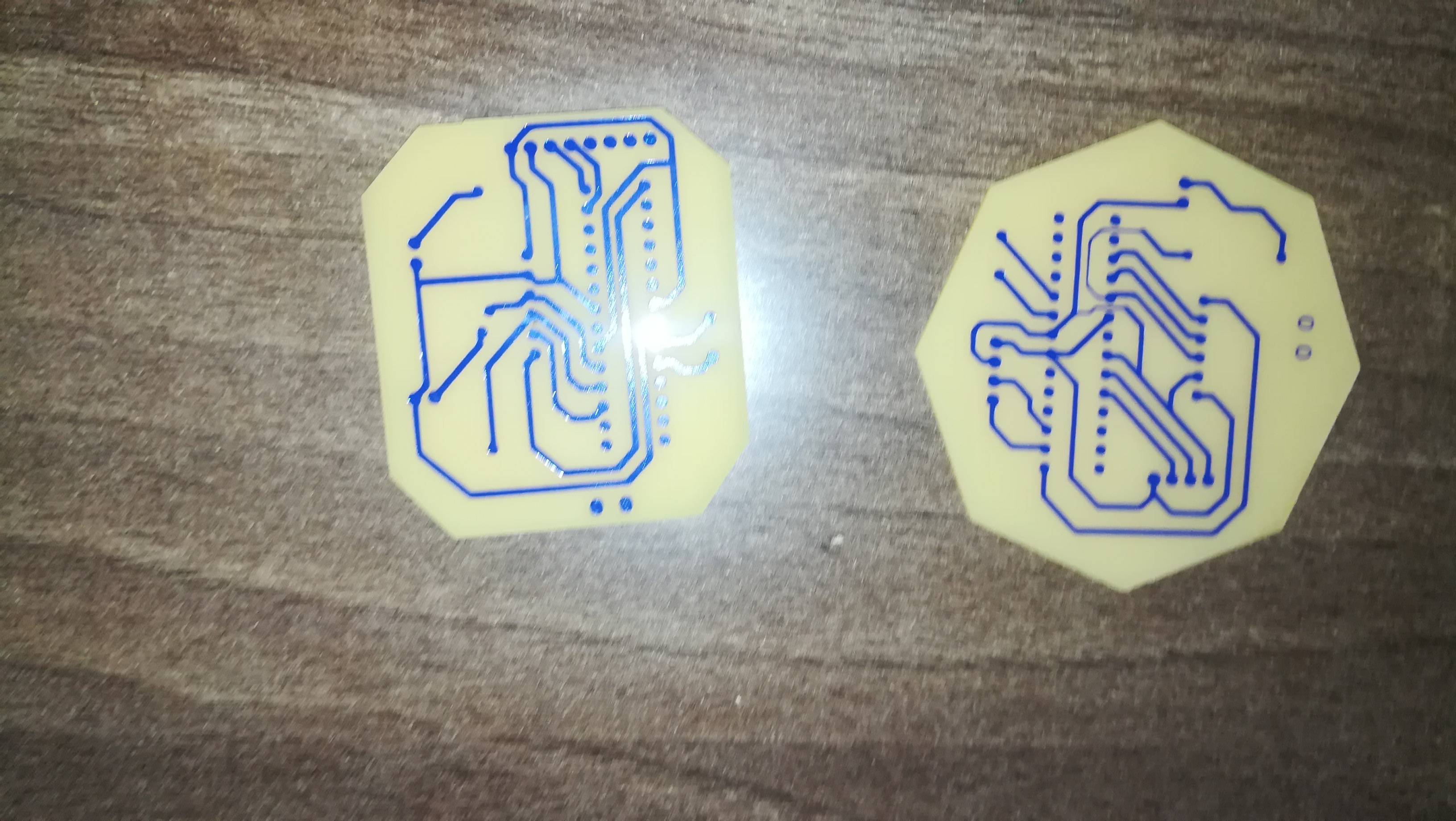
After finishing the schematic I designed the board as shown below. After finishing the design I exported to Pdf rather than png so as to get the actual board to scale. I then used a corel draw to create an outline and export the board to png for generating the nc codes using Fabmodules
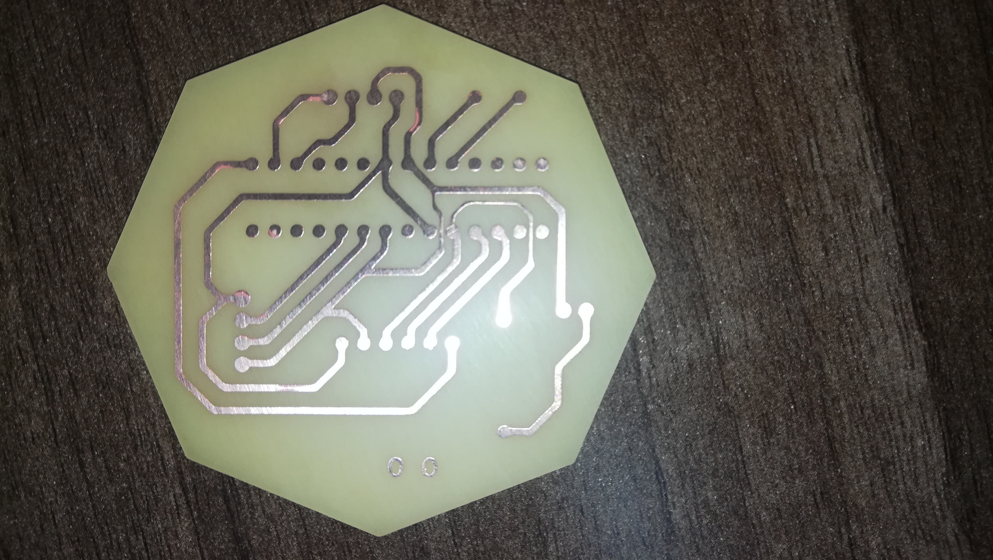
I then fabricated my board using the monofab SRM20
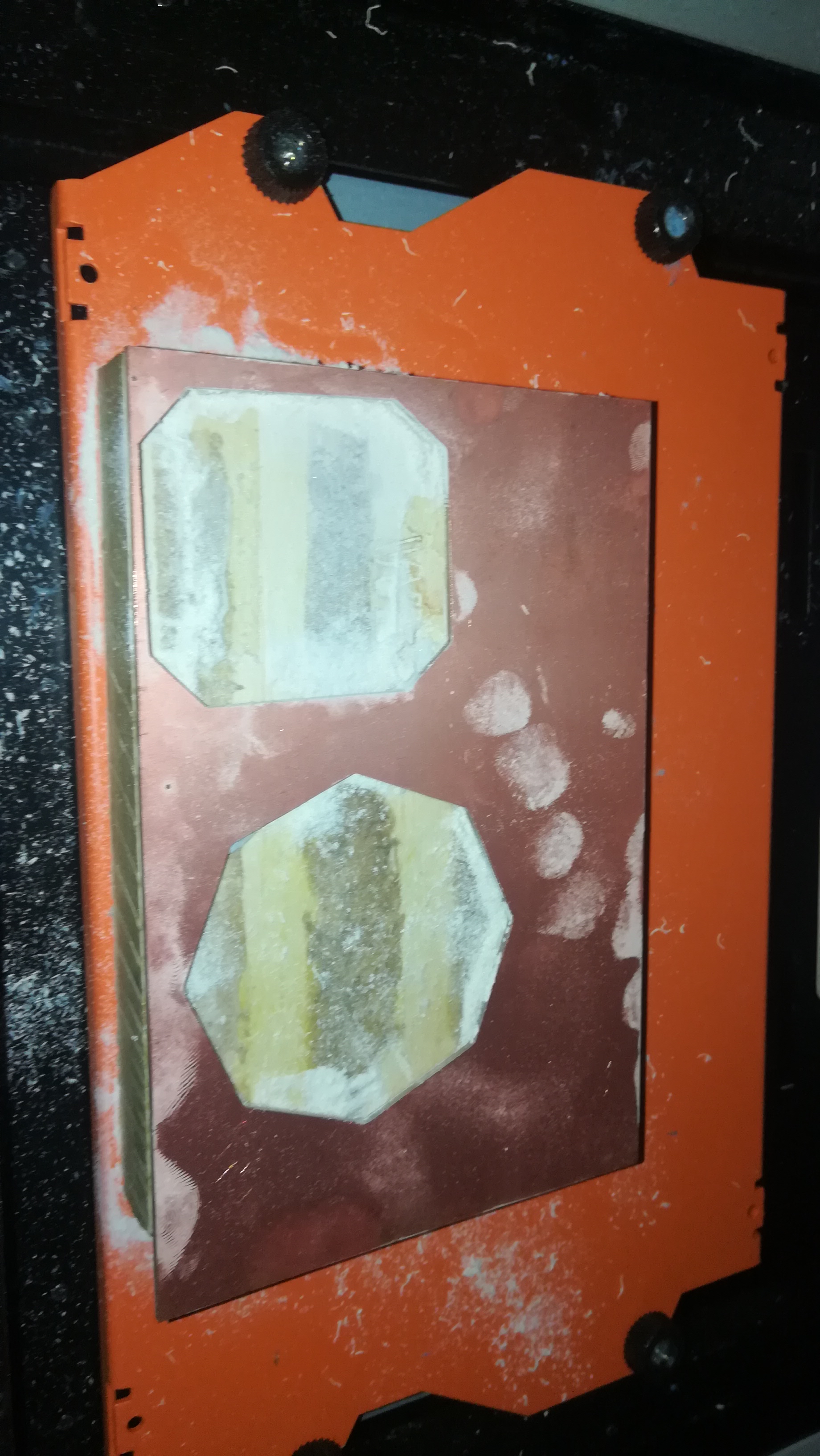
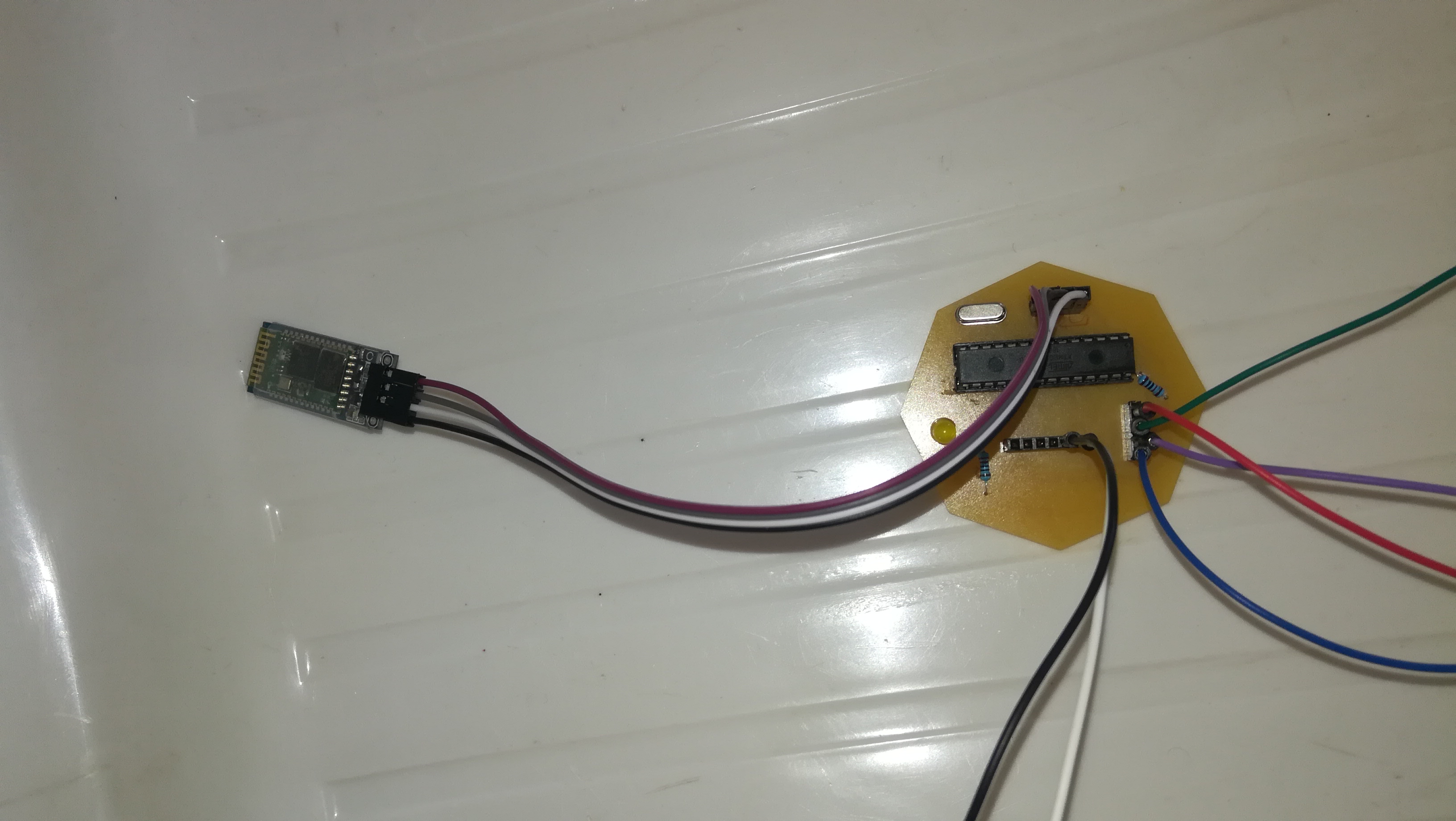
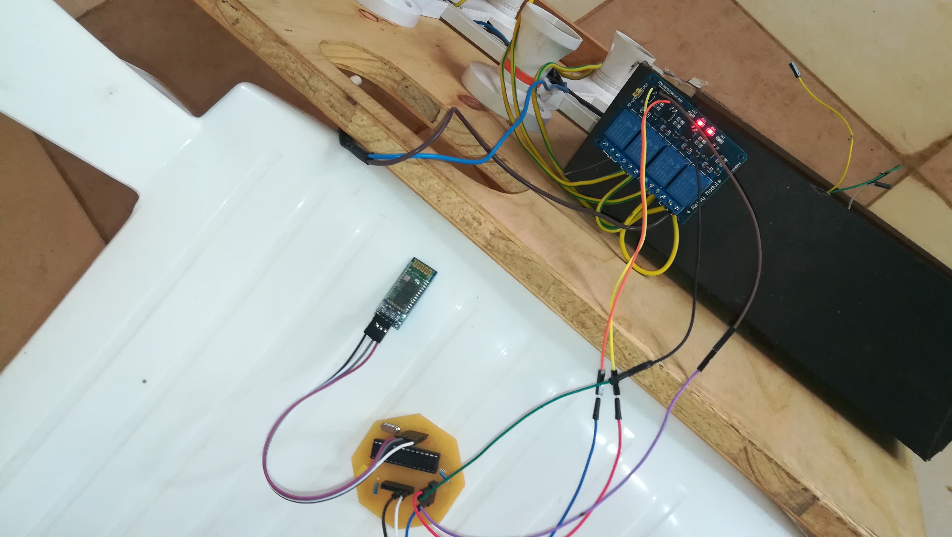
The final product is as shown below, I then went ahead to assemble my board and connect the various components.
From the diagram below you can see the HC-06 is connected from the left while the relay is connected from the top, and the programming pins are on the right. I first tested the board using blink sketch then went ahead to upload the code.
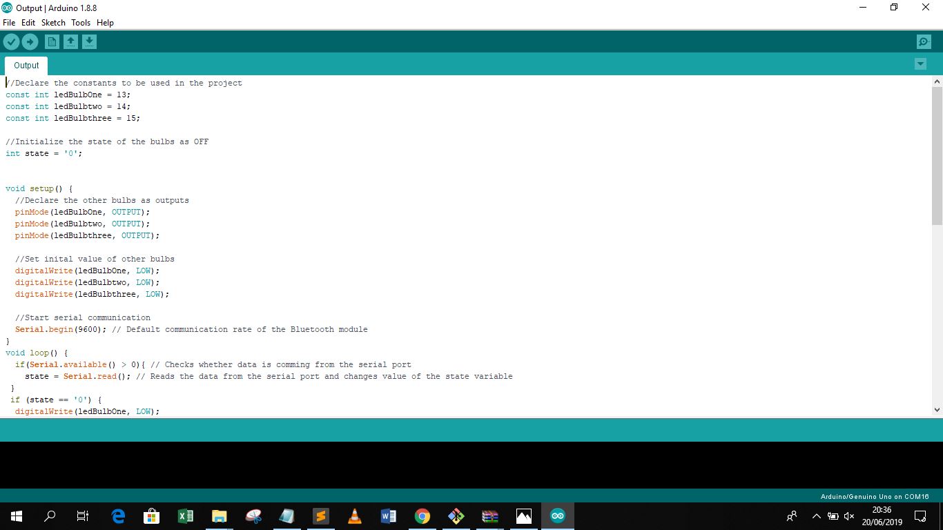
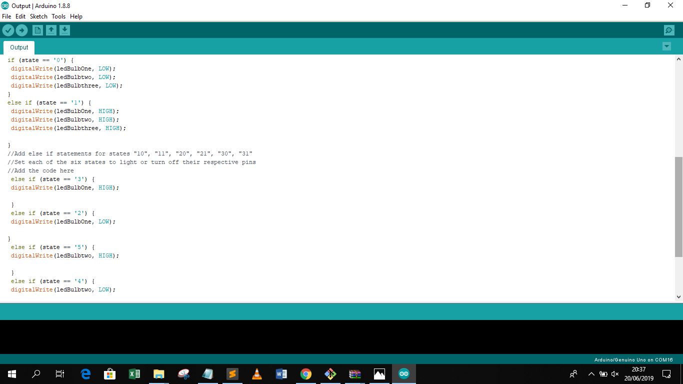
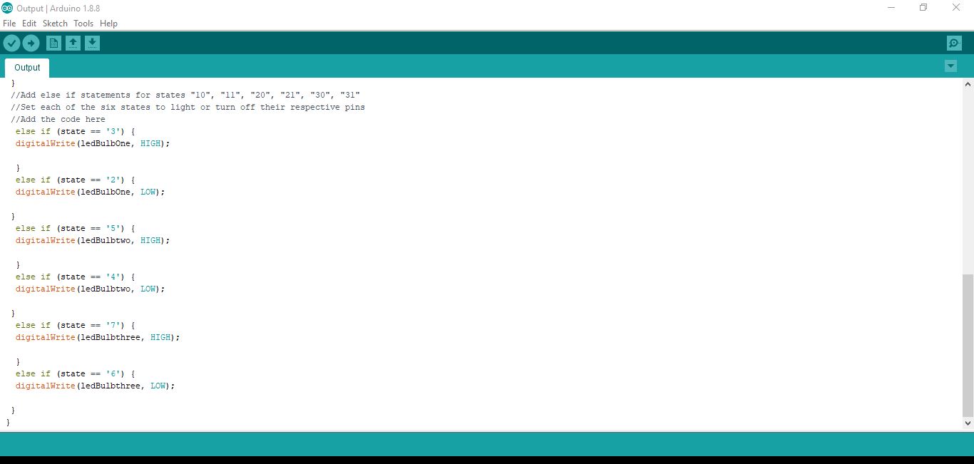
The code is as shown below: