Introduction
This weeks assignment is:
Measure something: add a sensor to a microcontroller board that you have designed and read it.
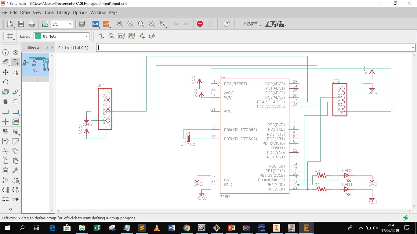
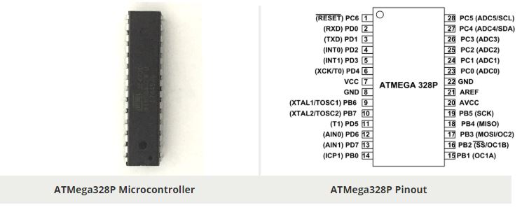
For this project I decided to use a readily available sensor within our lab which was the mpu6050 which doubles up as a gyroscope accelerometer and has a temperature sensor on board. I decided to use the sensor for the temperature function. The microcontroller i opted for was the Atmega328p which has the pinout indicated below.
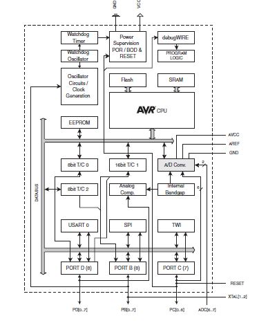
The block diagram of the microcontroller is as shown below
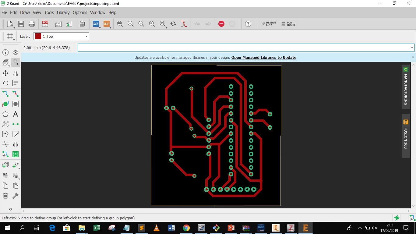
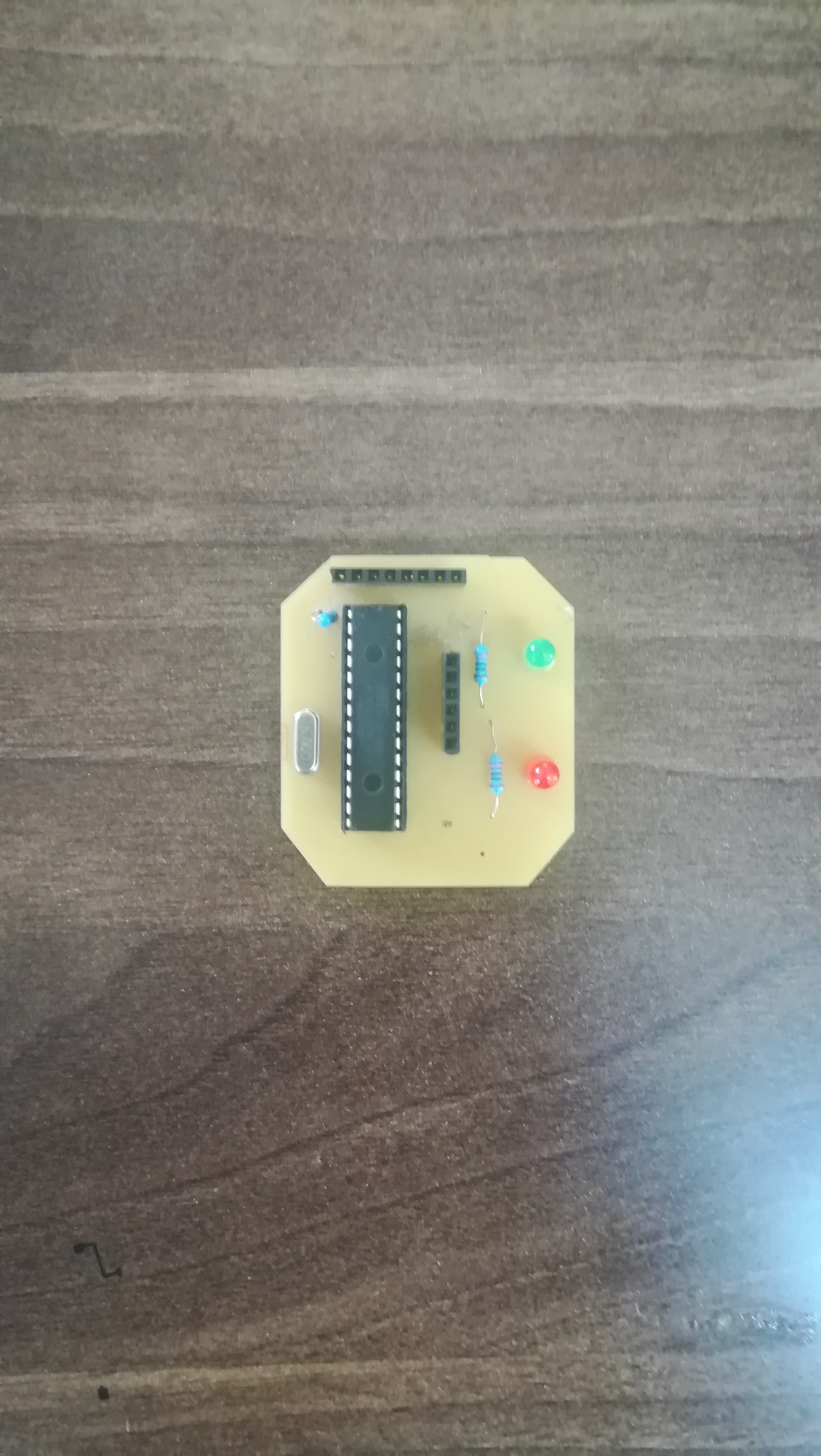
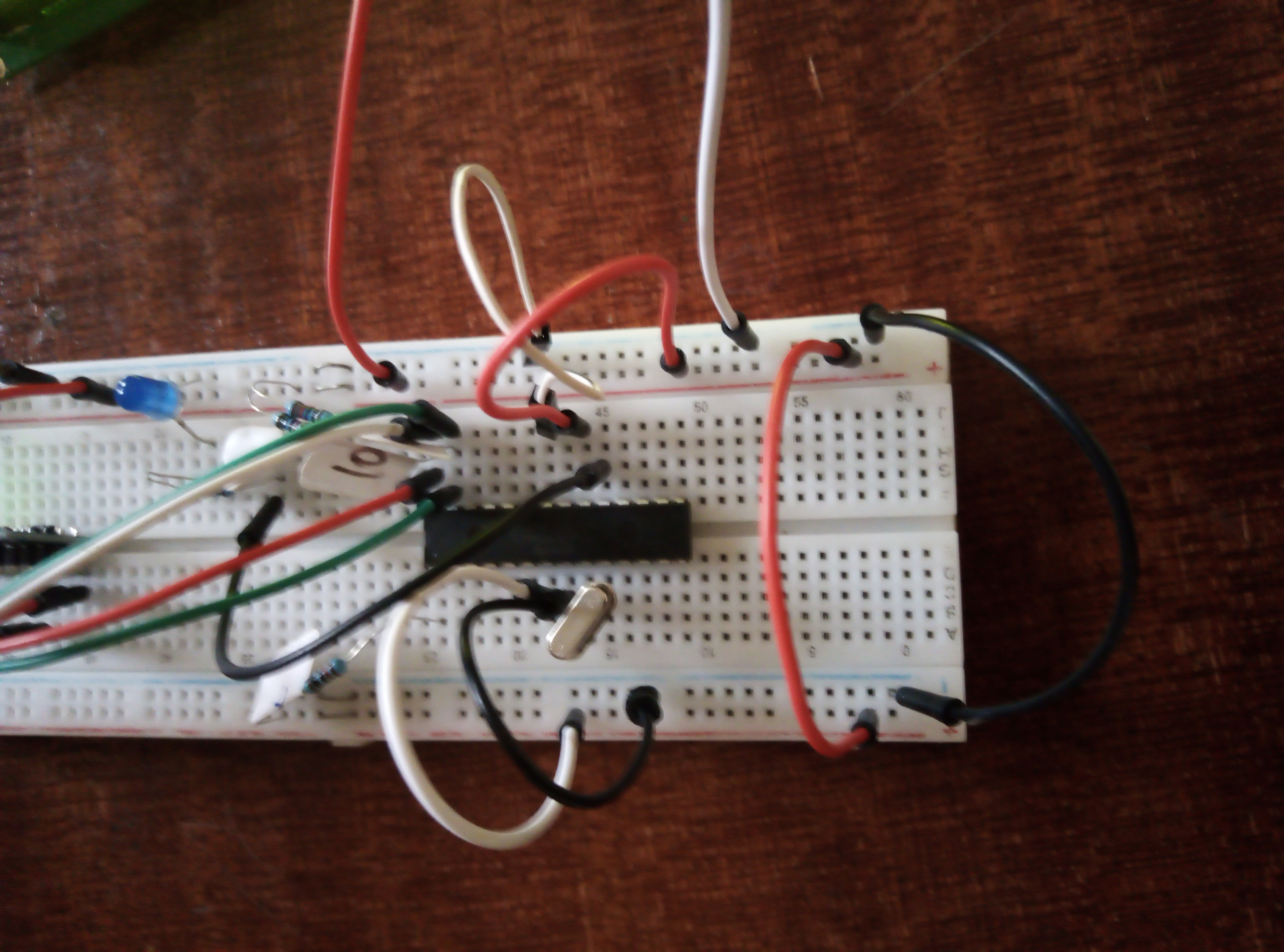
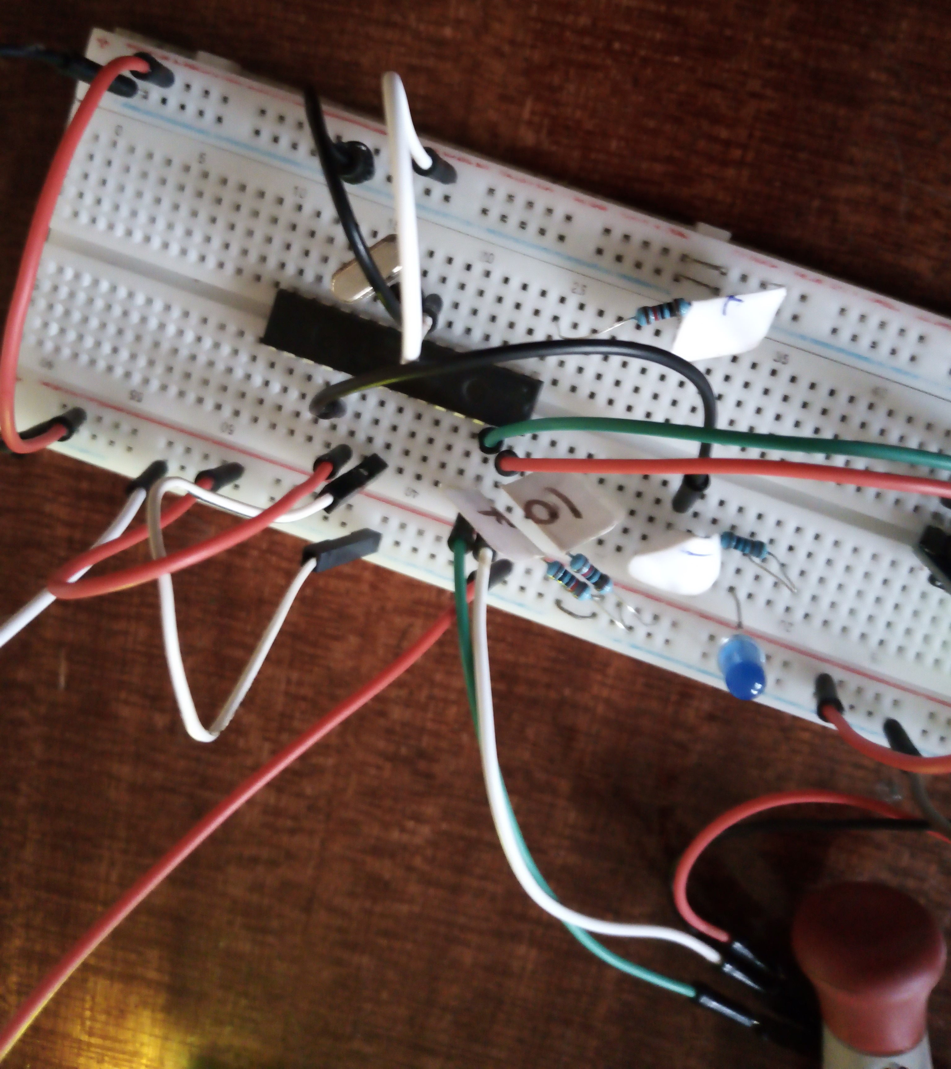
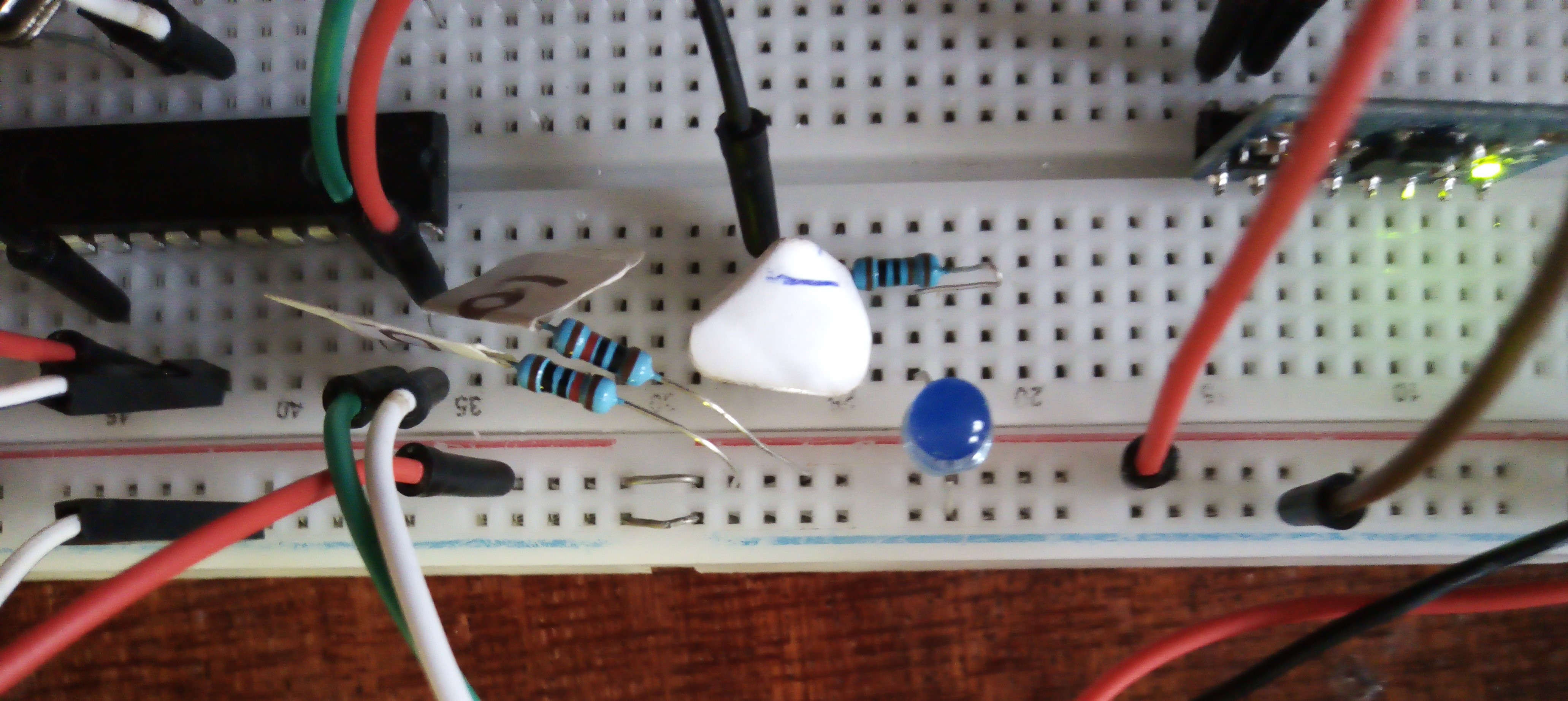
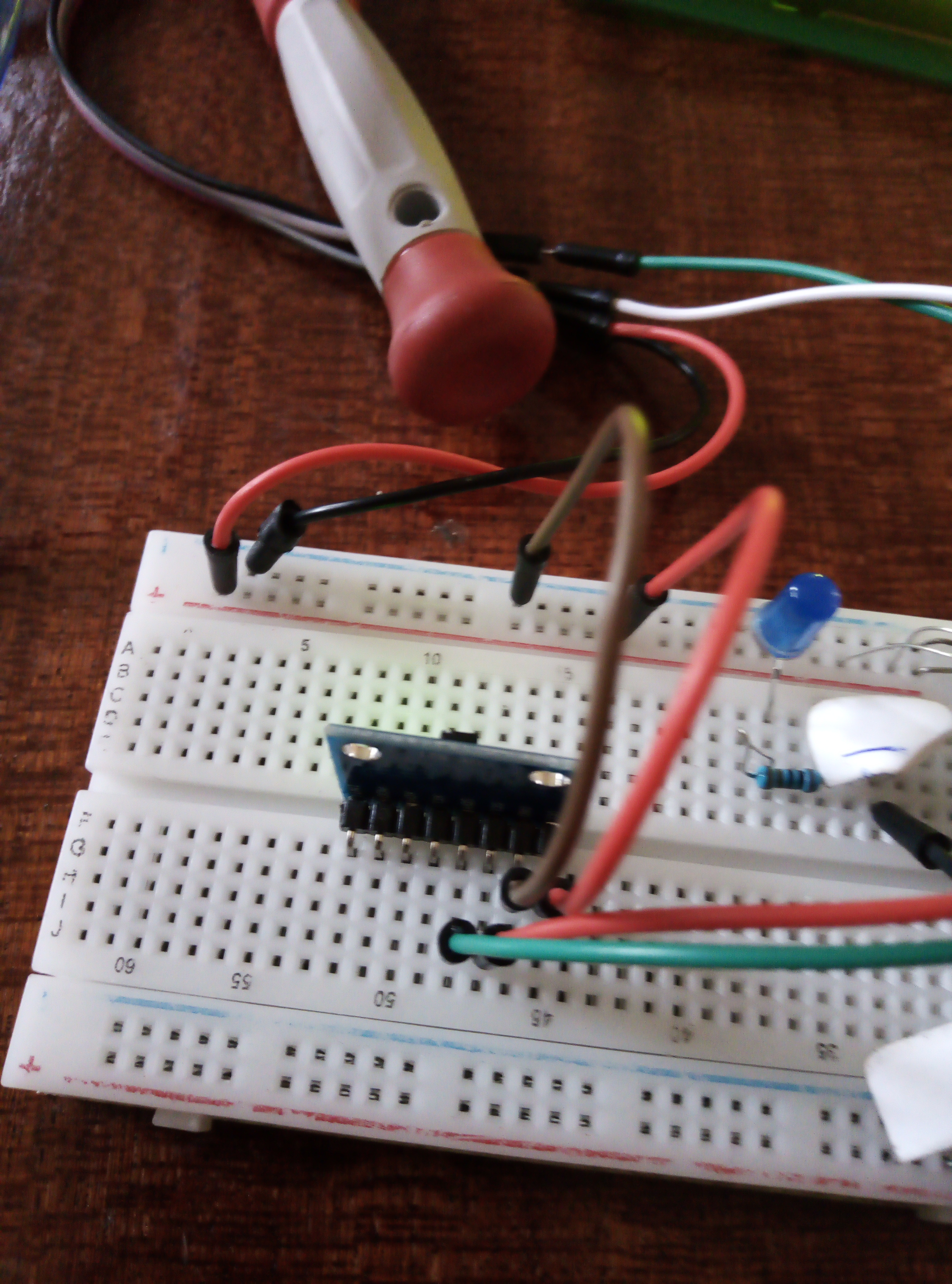
I connected the microcontroller to the board as shown below the circuit involves a connection of the mpu6050 at the scl and sda pins as well as ground and vcc same to the lcd screen.
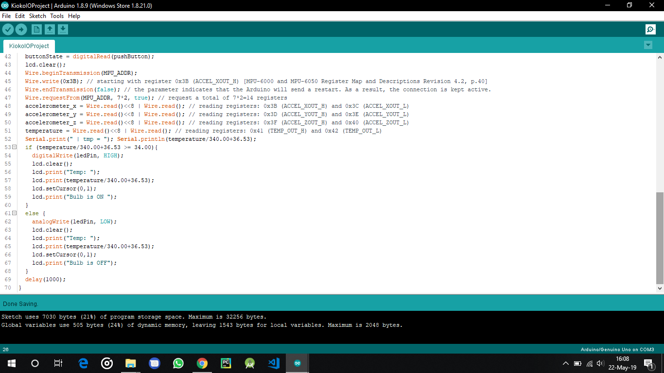
I used the arduino IDE to code the microcontroller and the function was supposed to light on an LED if the temperature exceeded 34 degrees and at the same time provide an output to the LCD screen. I then uploaded the code and the output is as shown in the video below the page
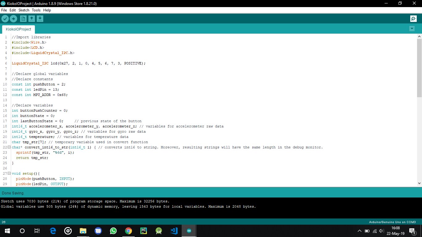
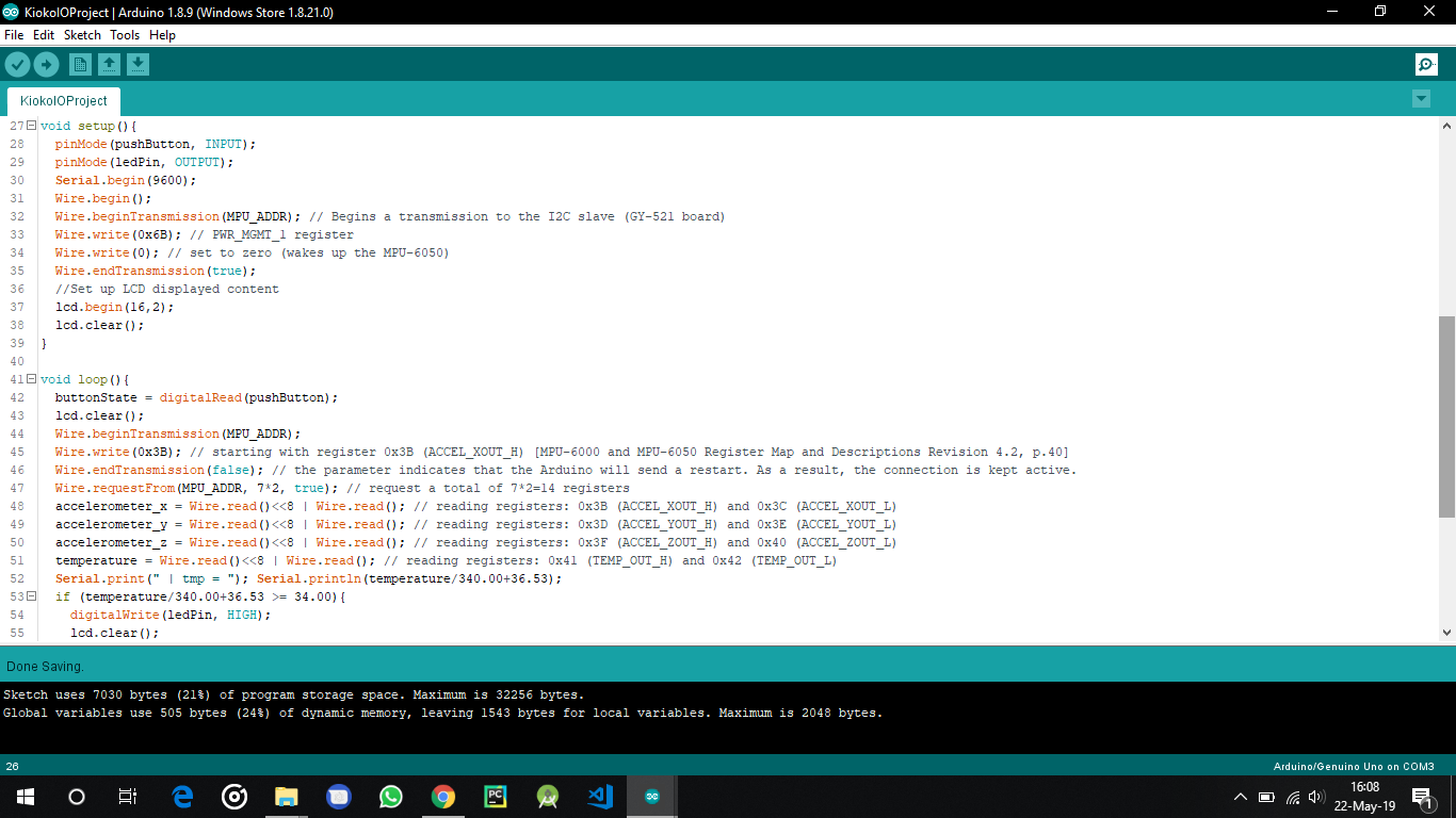
I encountered a challenge when connecting the two I2C devices (MPU and LCD) to the ATmega 328P since the microcontroller only has one set of SDA and SCL pins - pin 28 and 27 of the MC respectively. I solved the problem by connecting both the SDA pins of the MPU and LCD to pin 28 and their SCLs to pin 27. I then connected each of the respective pins (27 and 28) to a resistor and connected the other end of the resistors to the VCC.