The assignment for the week involved creating your own 3D object through moulding and casting. This required knowledge in CAD design and 3D modelling. In additon, it also required knowledge in milling and casting using epoxxy which was my casting medium selection.
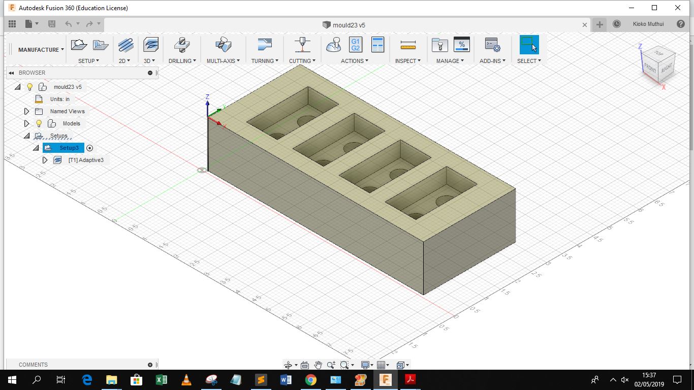
I designed a solid lego block, I designed the negative image of the block using Autodesk Fusion, since i could easily generate the NC code to be utilzed by the machine. The design was also based on the stock dimensions of the machinable wax which are 7" by 3" by 1.5".
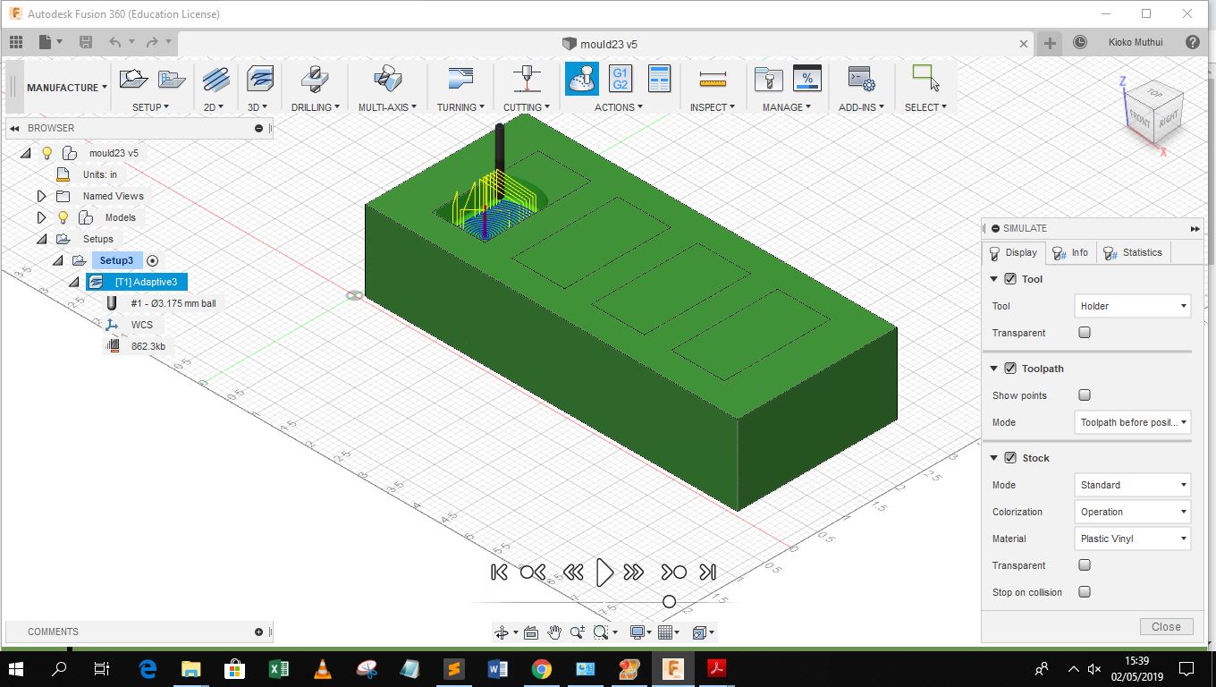
The next step involved using the Cam Processor for Autodesk Fusion to manufacture the part. This begun by creating the tool available at our Lab for use which is the 1/8" ball point mill.
After this I simulated the machine run from the origin point to see how it would cut the block and provide the finishing required.
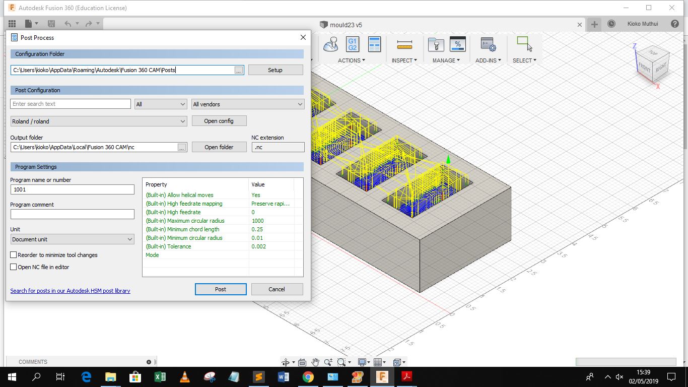
The next step involved post processing for the desired output machine which is the Roland Monofab SRM-20, The post processor of the machine however did not realize accurate machining as observed from a dry run using the Monofab SRM-20, The scale of the block was exagerated, in additon the origin setting was interprated inacurately. After further research online I decided to use the SRP Player.
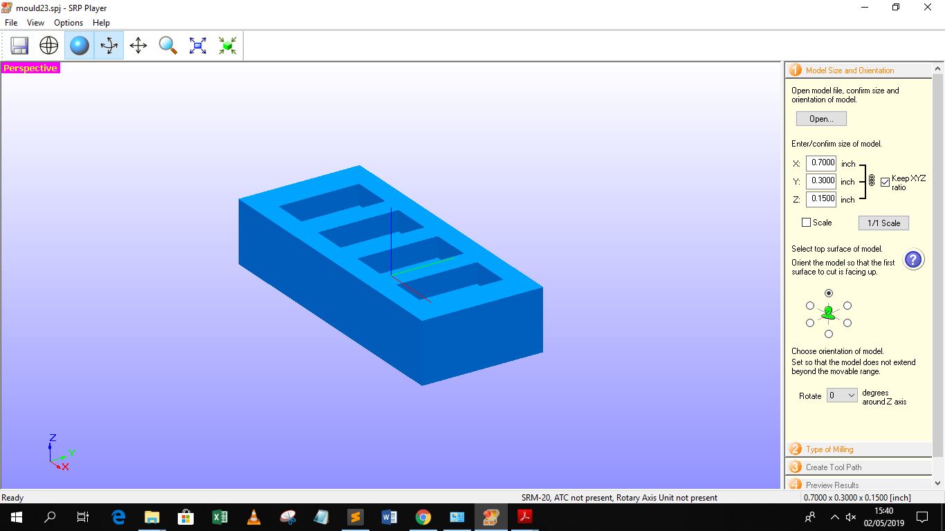
The SRP Player had a very easy to use interface as it only required me to choose the tool only, and define the block dimensions. The first step was however to export the object in an stl format from the CAD software used in my case was both Autodesk Inventor and Autodesk Fusion
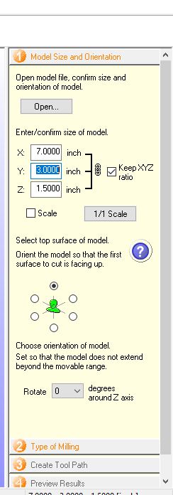 |
The next stages involved providing the size of the block and the scale if need be. The next stage involved providing the milling parameters for the operation |
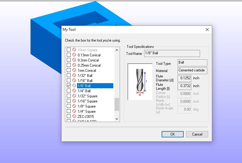
Before moving to the next operation it was important to select the tool one is using. This is important at this stage so as to avoid errors when generating the tool path which is the next stage after providing milling parameters. There is a library of tools provided by the SRP Player. However, if the tool you are using is not provided one can still add a new tool to the library and provide its specifications and cutting parameters. In my case the tool of choice is 1/8" ball end mill
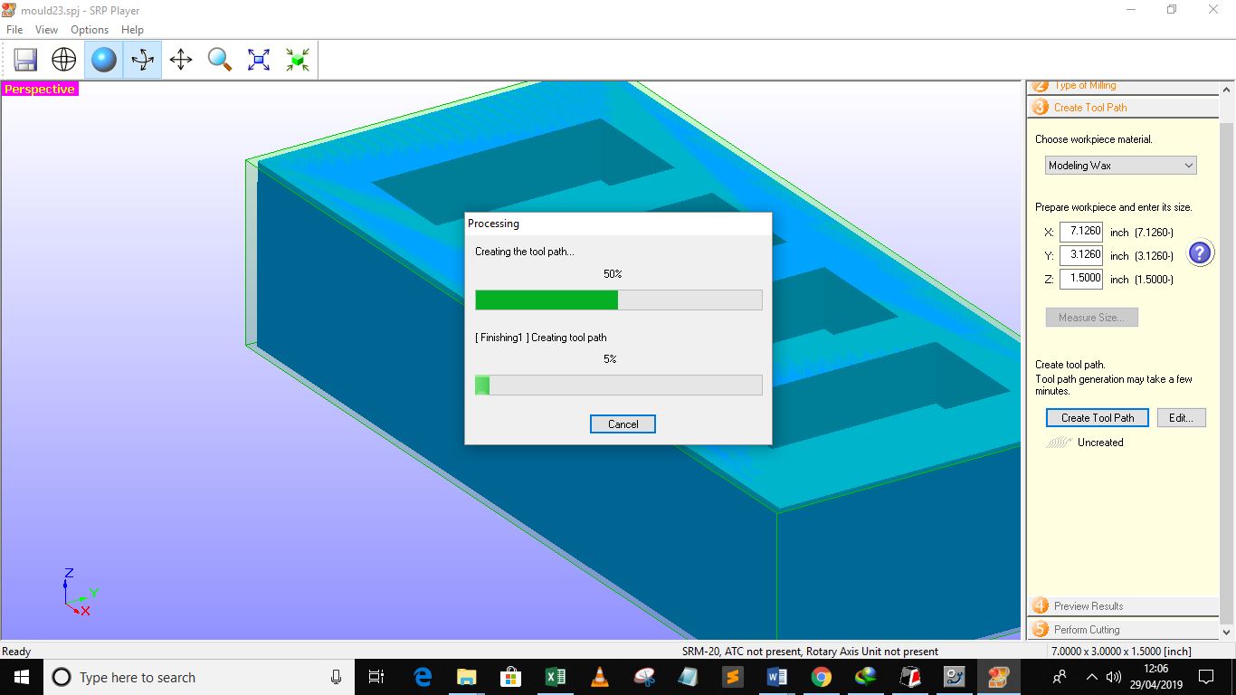
After selecting the tool, and indicating the milling parameter, the next stage is creating the tool path. The SRP generates the NC codes based on the parameters provided, the application also provides the user with options of customizing the tool path and operations to be done.
The next step is now to send the file to the Machine for cutting. It is importnat to have performed all machine prechecks and set ups before hand which mounting the workpiece and tool apropriately and setting the origin of the tool.
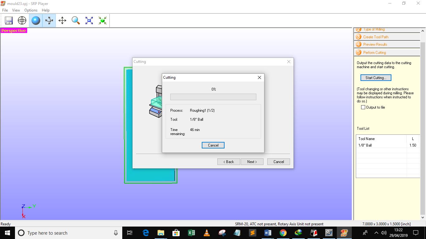
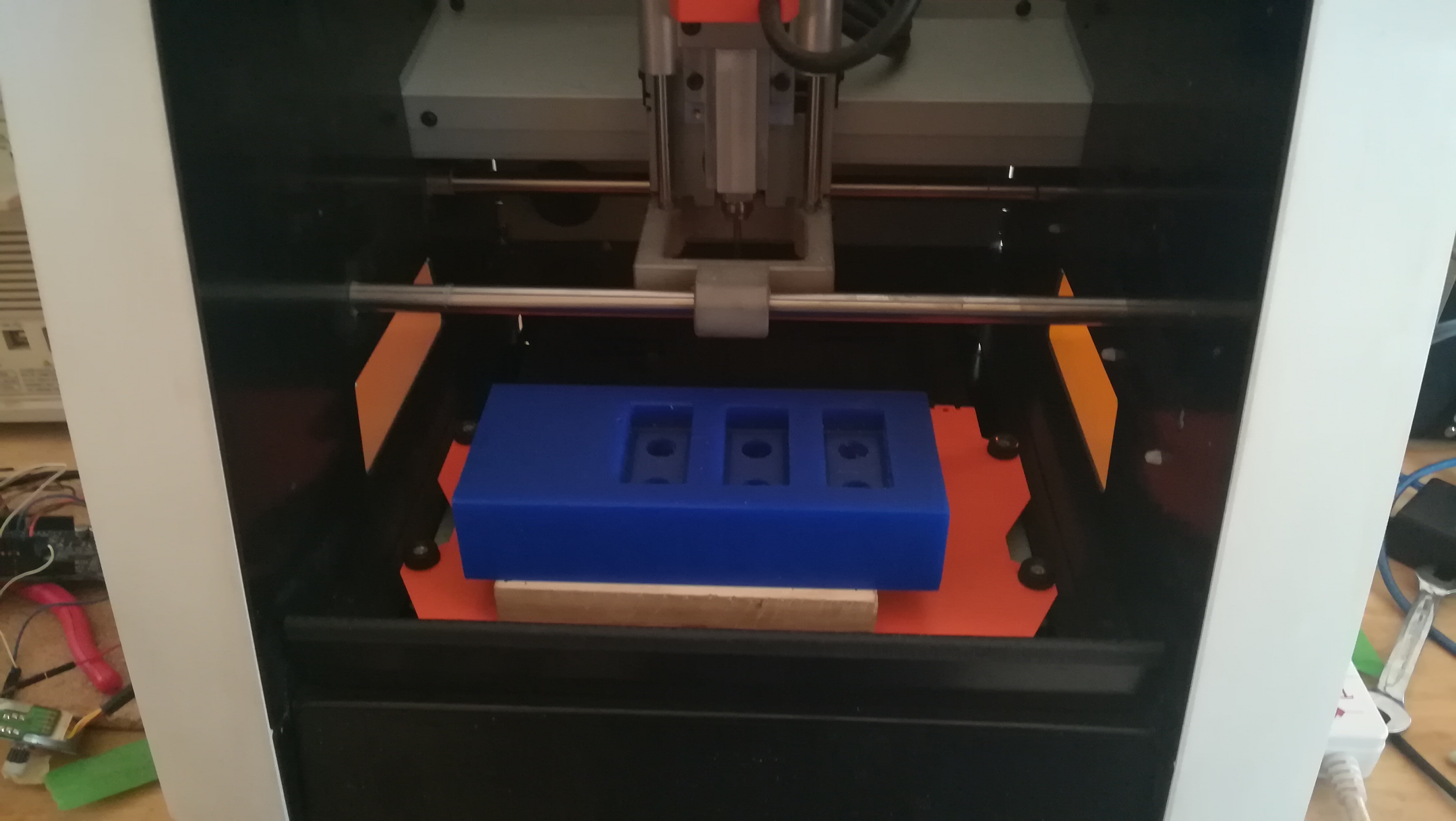
After ensuring all the parameters are set then the machining process can start. It is also importnat to set the origin of the machine to be as similar as that provided in the SRP player. Below is the final result of the machining process.
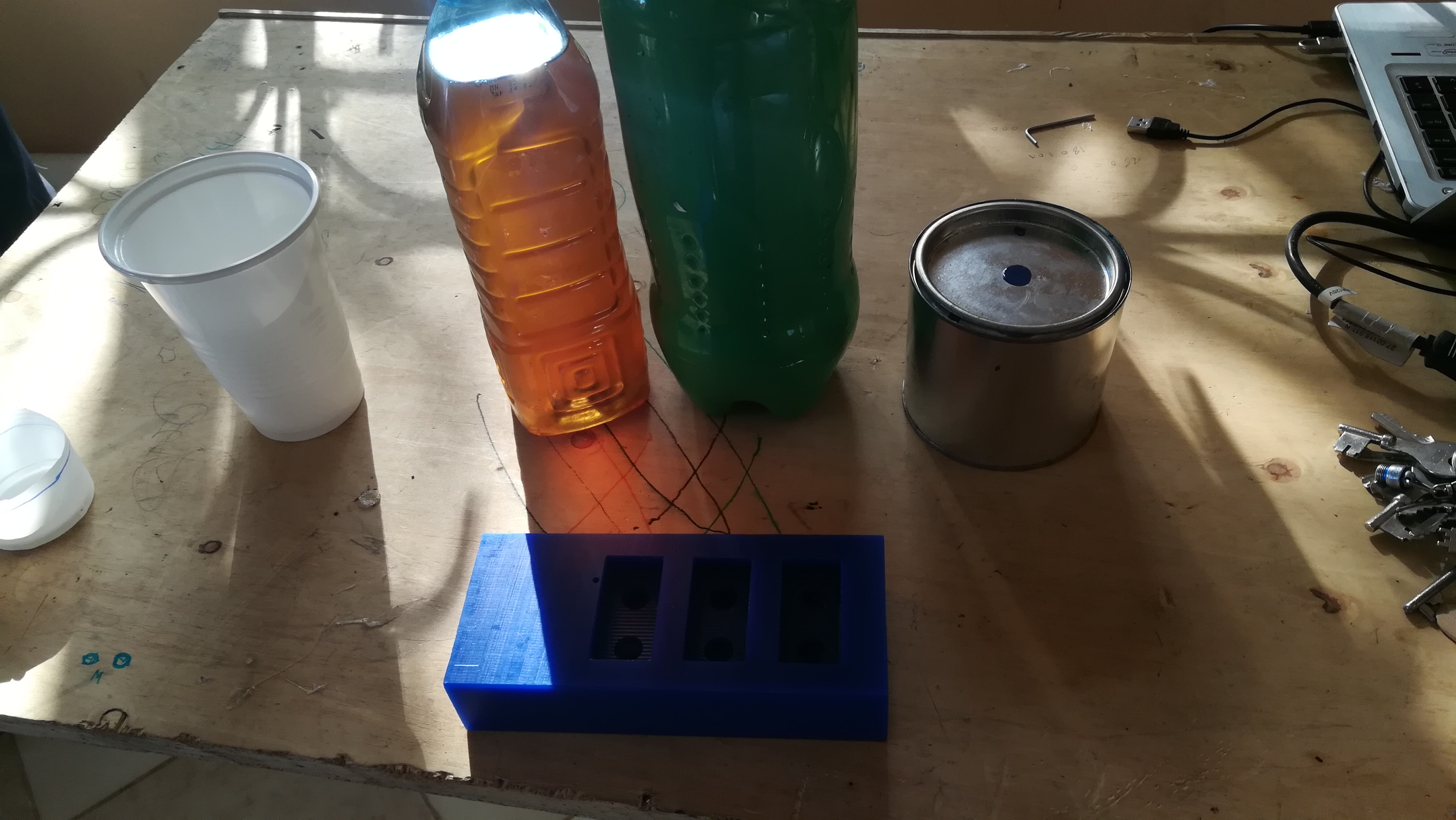
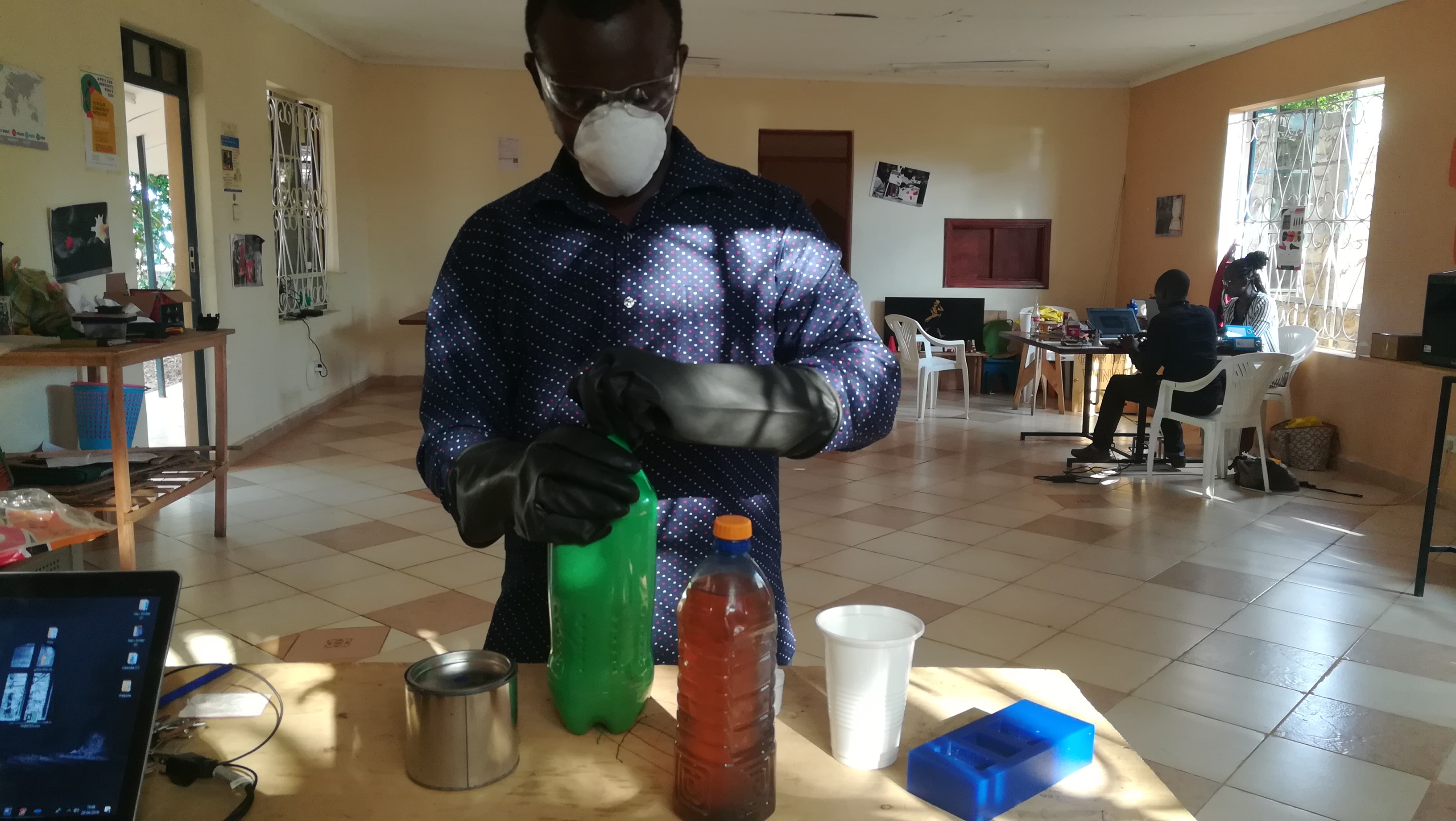
For casting I used epoxxy, and it was delivered in measured quantities to the lab. The epoxy was to be mixed in the ratio of 2:1. From the size of the bottles it is clear which bottle is for 2 and which one is for 1. I also used colour blue.
Based on the datasheet the material was to be handled using apropriate protective equipment which includes rubber gloves and masks.
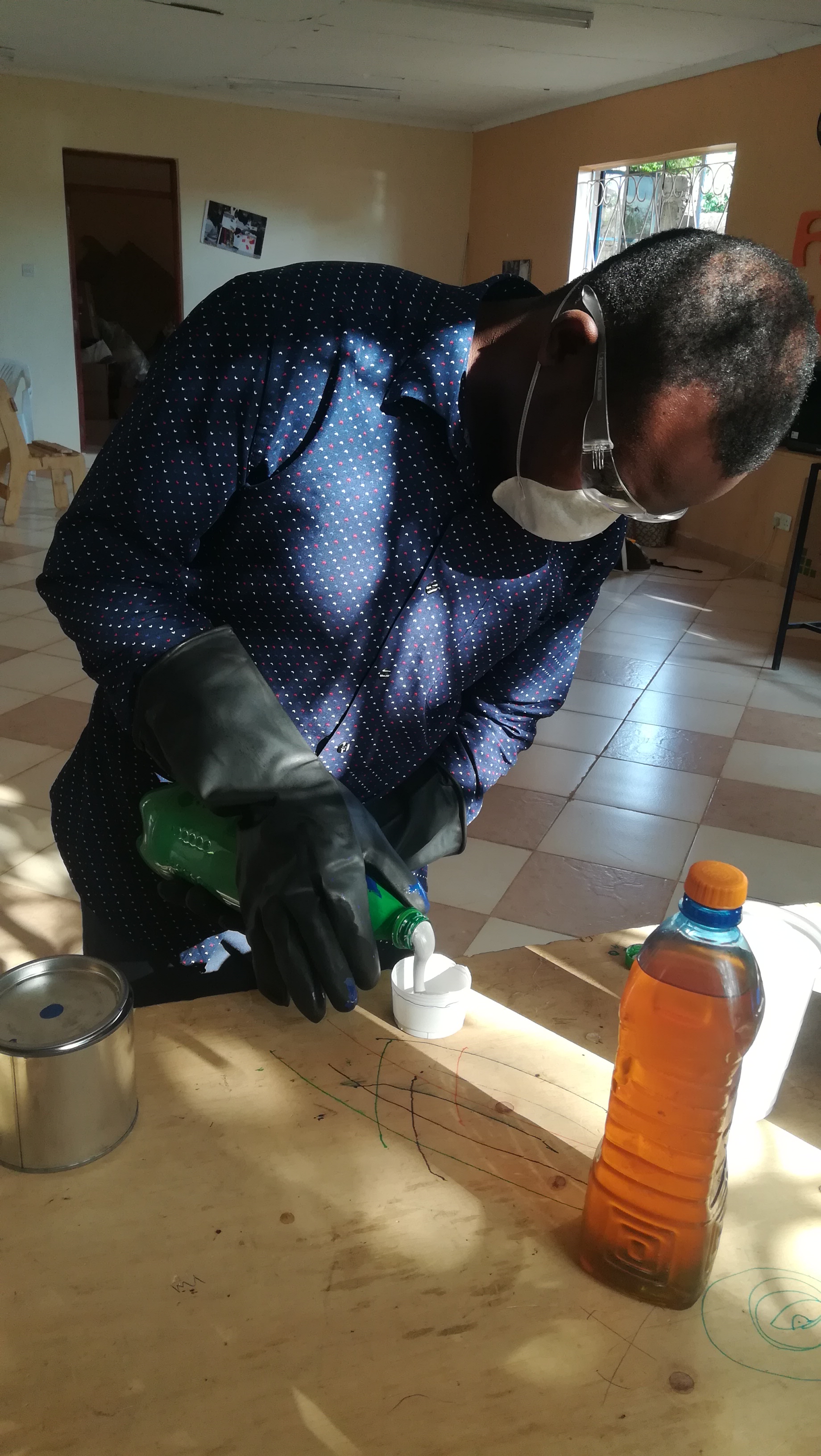
I created my own measuring container from disposable caps and poured 1 part of Solution A and 2 parts of Solution B in a measuring cylinder.
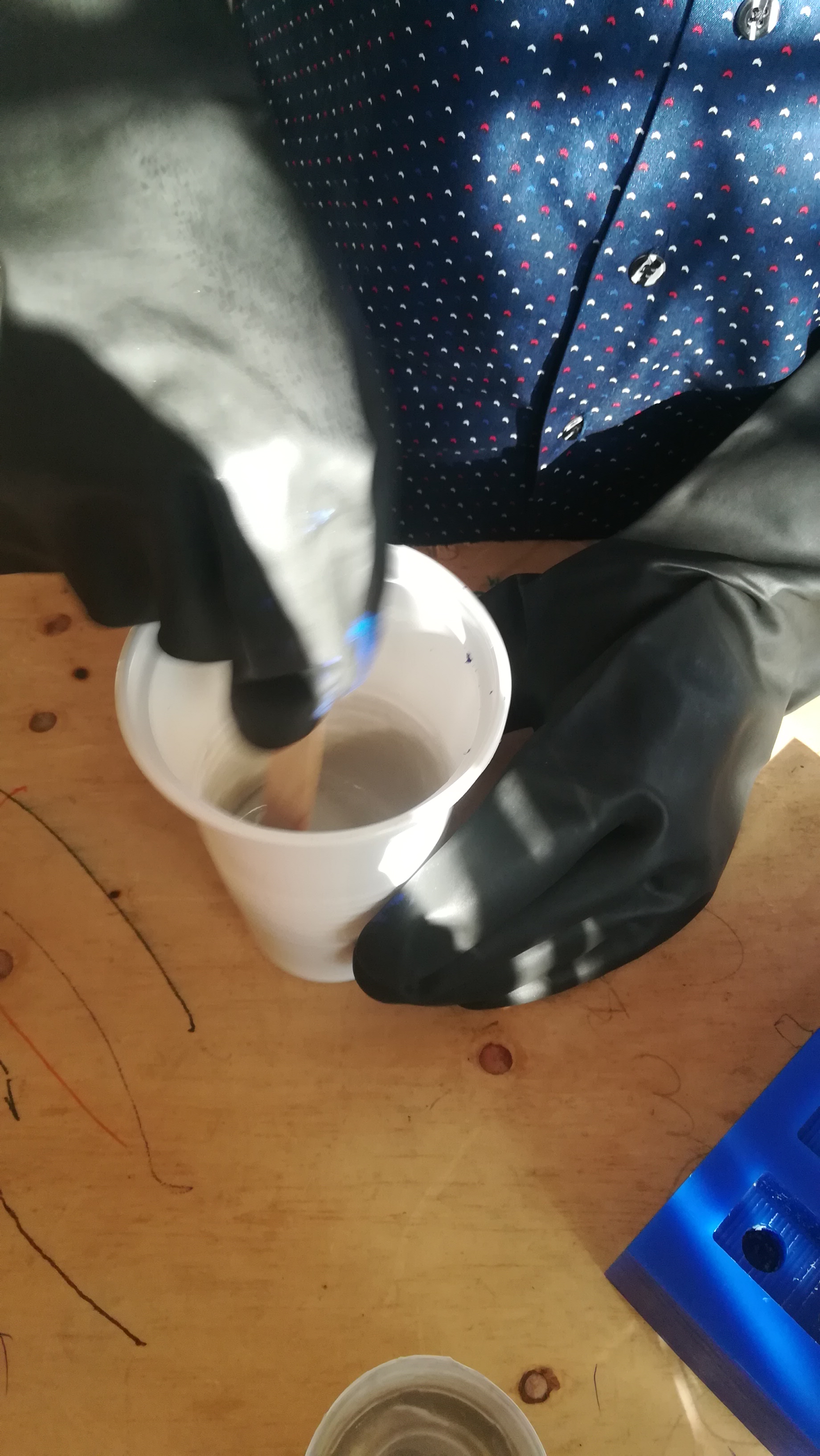
I then used a wooden spatula to thoroughly mix the solotion and added colour at the final stages of mixing.
I then poured the solution the mould cavity in the block, and let it dry for 48 hours.
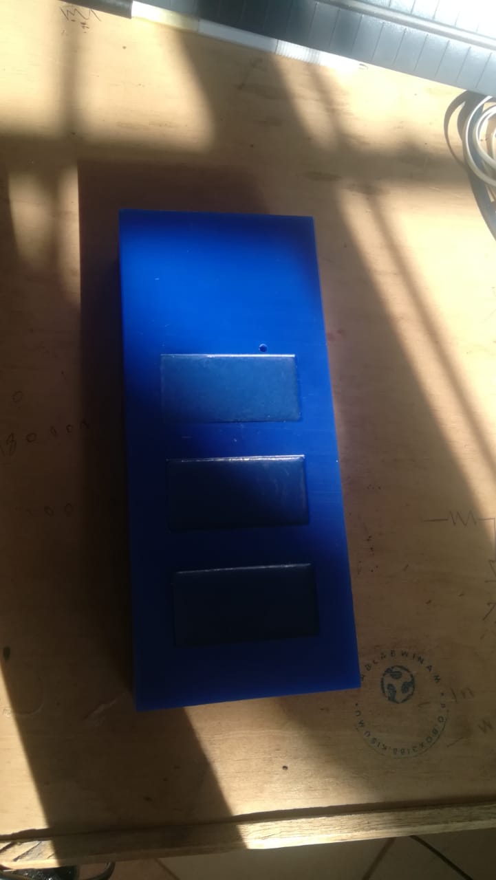
After 48 hours, I checked on my mould and it had dried, i then loosened the blocks and extracted them out.
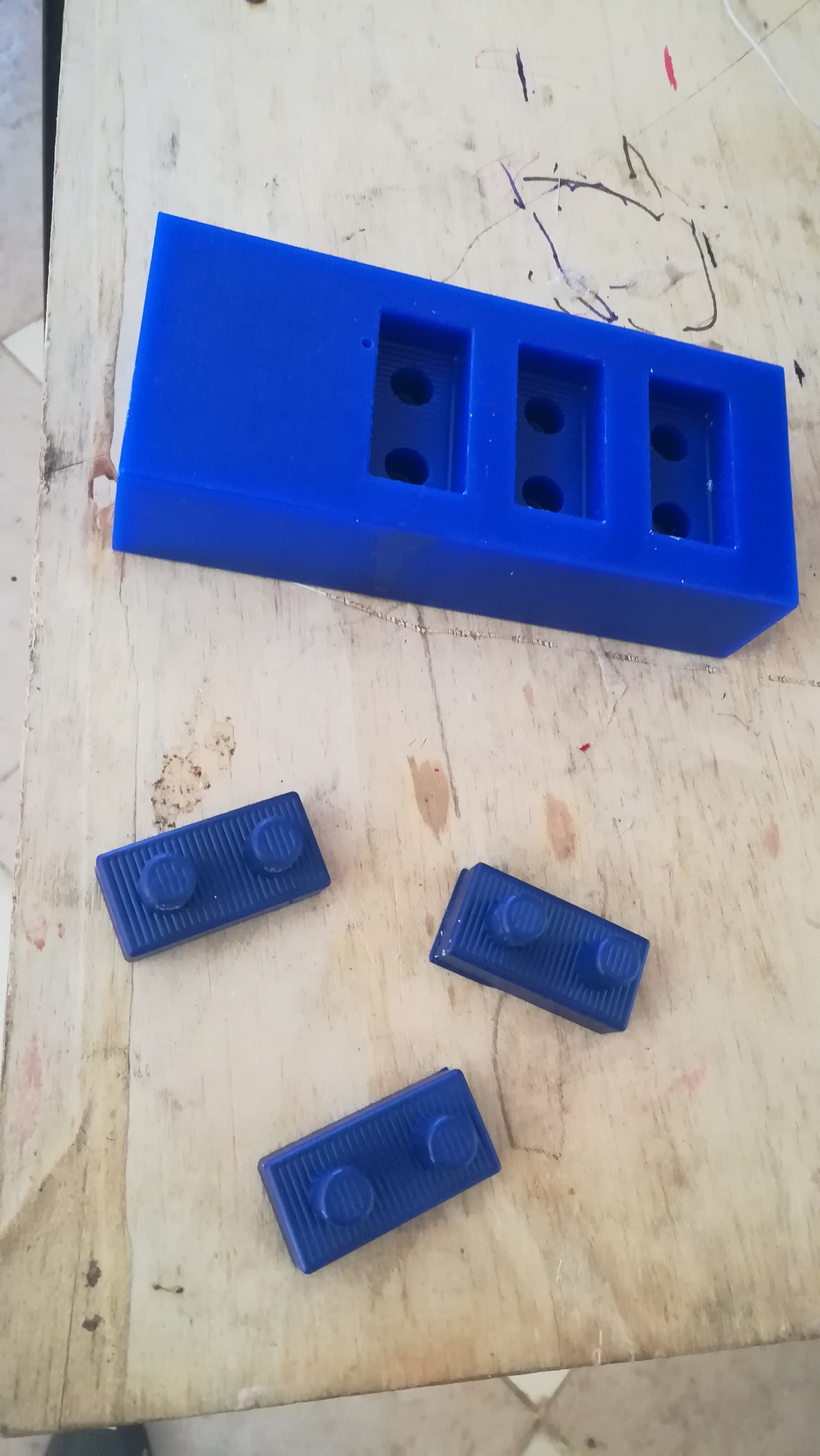
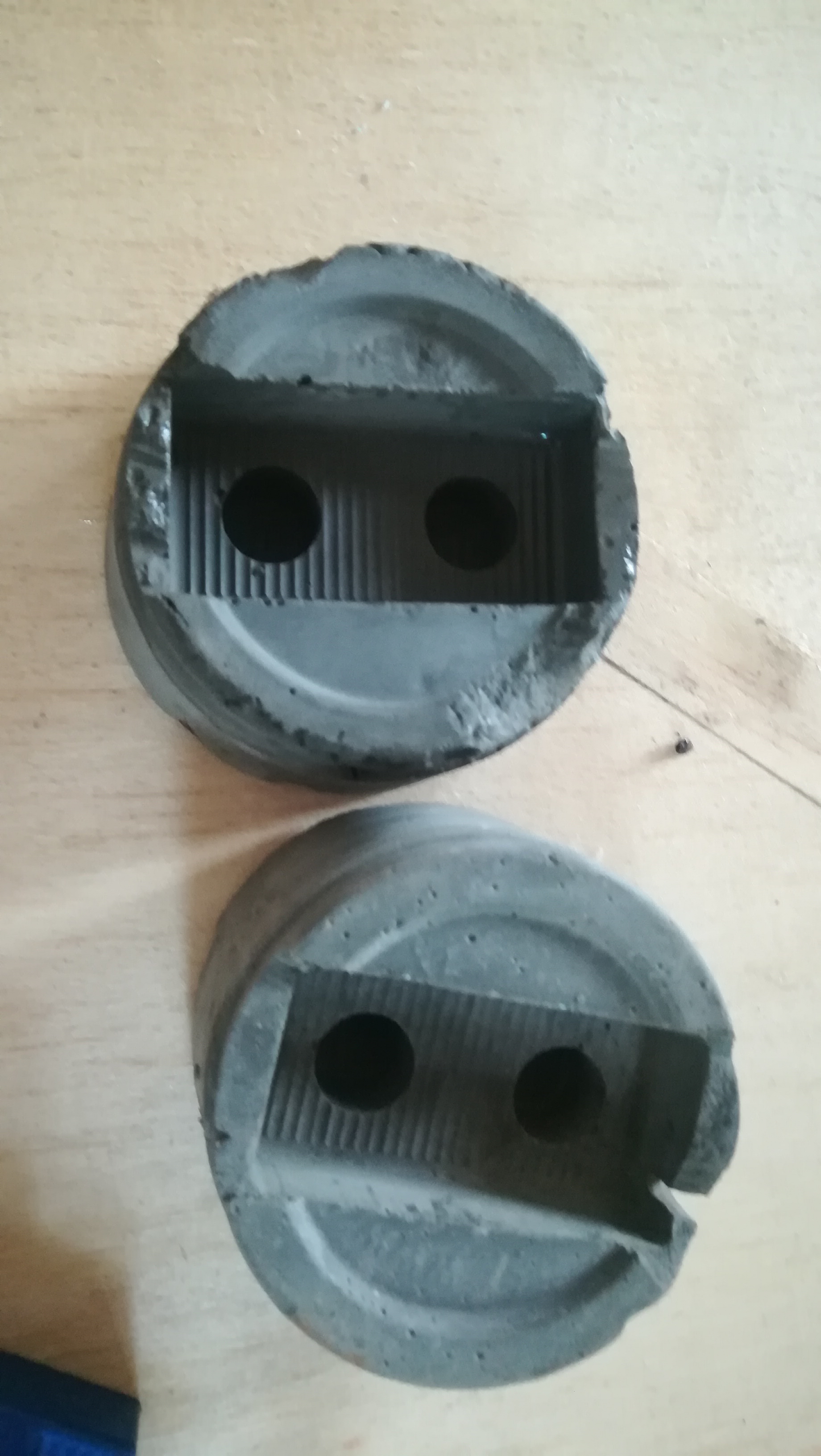
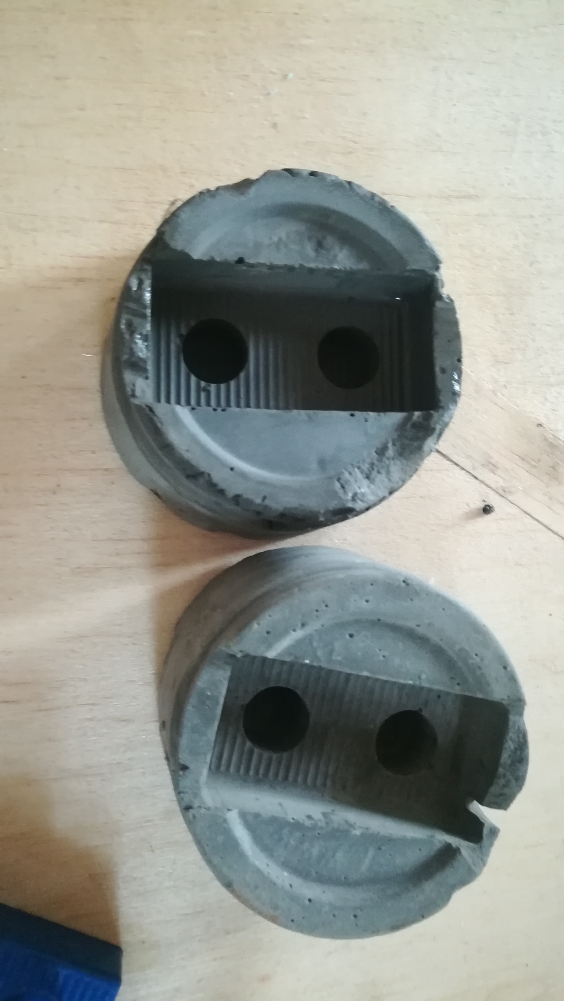
The next stage involved transfering the mould to the other part whereby i used concrete to mould cylindrical shapes of my mould. The outcome of the process is indicated below